
Inspiron 1300の取扱説明書・マニュアル [全44ページ 1.52MB]


0


18 / 44 ページ

18 / 44 ページ


現在のページURL
参考になったと評価  7人が参考になったと評価しています。
その他の取扱説明書

1642 view
このマニュアルの目次
-
1 .Dell™ Inspiron™ 1300/B120...Dell™ Inspiron™ 1300/B120/B130 Service ManualBefore You BeginHingeSystem ComponentsBatteryMemory, Optical Drive, and Mini PCI CardHard DriveKeyboardDisplay AssemblyPalm RestModemCoin-Cell BatteryMicroprocessor Thermal-Cooling AssemblyMicroprocessor Module...
-
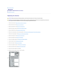
2 .Back to Contents Page An...Back to Contents Page AntennaDell™ Inspiron™ 1300/B120/B130 Service Manual Replacing the Antenna Replacing the Antenna CAUTION: Before performing the following procedures, read the safety instructions in the Product Information Guide. CAUTION: To preven...
-
4 .Back to Contents Page Ba...Back to Contents Page Base PlasticsDell™ Inspiron™ 1300/B120/B130 Service Manual CAUTION: Before performing the following procedures, read the safety instructions in the Product Information Guide. CAUTION: To prevent static damage to components inside yo...
-
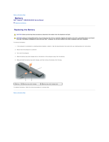
5 .Back to Contents Page Ba...Back to Contents Page BatteryDell™ Inspiron™ 1300/B120/B130 Service Manual Replacing the Battery Replacing the Battery CAUTION: Before performing these procedures, disconnect the modem from the telephone wall jack. CAUTION: Using an incompatible battery...
-
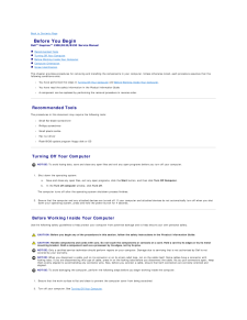
6 .Back to Contents Page Be...Back to Contents Page Before You BeginDell™ Inspiron™ 1300/B120/B130 Service Manual Recommended Tools Turning Off Your Computer Before Working Inside Your Computer Computer Orientation Screw IdentificationThis chapter provides procedures for removin...
-
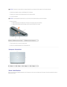
7 .NOTICE: To disconnect a n...NOTICE: To disconnect a network cable, first unplug the cable from your computer and then unplug it from the network wall jack.3. Disconnect any telephone, network, and USB cables from the computer.4. Disconnect your computer and all attached devices from ...
-
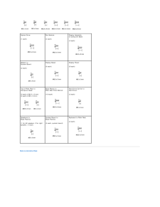
8 .Optical Drive:Fan Module:...Optical Drive:Fan Module:(1 each)Display Assemblyto Computer Base:(4 each)(4 each) Modem toSystem Board: Display Bezel:Display Panel:(6 each)(8 each)(2 each) Top of Palm Rest toComputer Base:Base Plastic toPalm Rest From Bottom:Hard Drive Carrier toHard D...
-
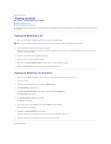
9 .Back to Contents Page Fl...Back to Contents Page Flashing the BIOSDell™ Inspiron™ 1300/B120/B130 Service Manual Flashing the BIOS From a CD Flashing the BIOS From the Hard DriveIf a BIOS-update program CD is provided with the new system board, flash the BIOS from the CD. If you ...
-
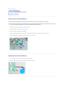
10 .Back to Contents Page Co...Back to Contents Page Coin-Cell BatteryDell™ Inspiron™ 1300/B120/B130 Service Manual Removing the Coin-Cell Battery Replacing the Coin-Cell Battery Removing the Coin-Cell Battery CAUTION: Before performing the following procedures, read the safety inst...
-
12 .Back to Contents Page Mi...Back to Contents Page Microprocessor ModuleDell™ Inspiron™ 1300/B120/B130 Service Manual Removing the Microprocessor Module Installing the Microprocessor Module Removing the Microprocessor Module CAUTION: Before performing the following procedures, rea...
-
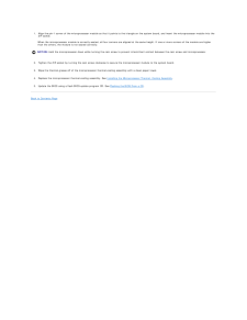
13 .1. Align the pin-1 corner...1. Align the pin-1 corner of the microprocessor module so that it points to the triangle on the system board, and insert the microprocessor module into theZIF socket.When the microprocessor module is correctly seated, all four corners are aligned at the sa...
-
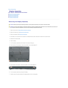
14 .Back to Contents Page Di...Back to Contents Page Display AssemblyDell™ Inspiron™ 1300/B120/B130 Service Manual Removing the Display Assembly Removing the Display Bezel Removing the Display Panel Installing the Display Panel Removing the Display Assembly CAUTION: Before perform...
-
15 .1antenna cable1antenna ca...1antenna cable1antenna cable22display cabledisplay cable pull tab NOTICE: Be careful not to damage the display switch when removing the display.12. Lift the display assembly out of the computer base. Removing the Display Bezel CAUTION: Before performing...
-
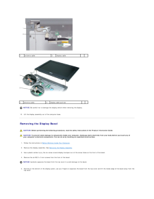
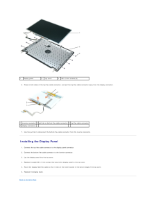
16 .1screw covers/display bum...1screw covers/display bumpers (6)2M2.5 x 5-mm screws (6)3display bezel4top cover Removing the Display Panel CAUTION: Before performing the following procedures, read the safety instructions in the Product Information Guide. CAUTION: To prevent static d...
-
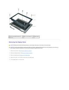
17 .1display panel6.2top cove...1display panel6.2top cover3M2 x 3-mm screws (8) Press in both sides of the top flex-cable connector, and pull the top flex-cable connector away from the display connector.1 inverter connector 2 pull-tab on bottom flex-cable connector 3 top flex-cable conne...
-
18 .18 ページ目のマニュアル
-
19 .Back to Contents Page Fa...Back to Contents Page FanDell™ Inspiron™ 1300/B120/B130 Service Manual Removing the Cooling Fan Installing the Cooling Fan Removing the Cooling Fan CAUTION: Before performing the following procedures, read the safety instructions in the Product Informa...
-
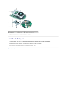
20 .1fan assembly17.2metal pl...1fan assembly17.2metal plate3M2.5 x 5-mm screws (4) Remove the plate and lift the system board off the fan assembly. Installing the Cooling Fan1. Position the system board over the fan assembly, aligning the screw holes in the system board with those in th...
-
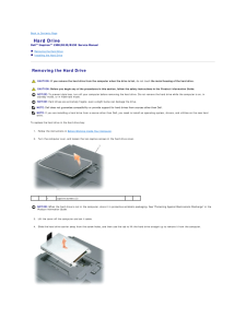
21 .Back to Contents Page Ha...Back to Contents Page Hard DriveDell™ Inspiron™ 1300/B120/B130 Service Manual Removing the Hard Drive Installing the Hard Drive Removing the Hard Drive CAUTION: If you remove the hard drive from the computer when the drive is hot, do not touch the meta...
-
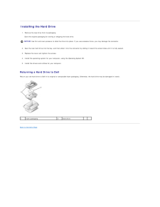
22 .Installing the Hard Driv...Installing the Hard Drive1. Remove the new drive from its packaging.Save the original packaging for storing or shipping the hard drive.NOTICE: Use firm and even pressure to slide the drive into place. If you use excessive force, you may damage the connect...
-
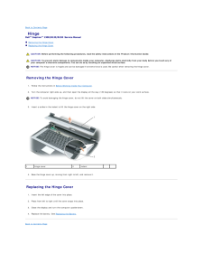
23 .Back to Contents Page Hi...Back to Contents Page HingeDell™ Inspiron™ 1300/B120/B130 Service Manual Removing the Hinge Cover Replacing the Hinge Cover CAUTION: Before performing the following procedures, read the safety instructions in the Product Information Guide. CAUTION: To ...
-
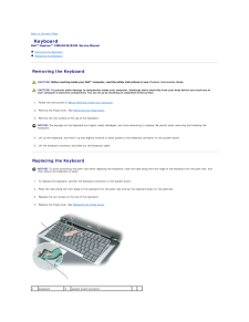
24 .Back to Contents Page Ke...Back to Contents Page KeyboardDell™ Inspiron™ 1300/B120/B130 Service Manual Removing the Keyboard Replacing the Keyboard Removing the Keyboard CAUTION: Before working inside your Dell™ computer, read the safety instructions in your Product Information ...
-
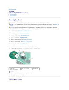
26 .Back to Contents Page Mo...Back to Contents Page ModemDell™ Inspiron™ 1300/B120/B130 Service Manual Removing the Modem Replacing the Modem Removing the Modem CAUTION: Before you begin the following procedure, see the safety instructions in the Product Information Guide.NOTICE: T...
-
27 .1.Connect the modem cable...1.Connect the modem cable to the modem.NOTICE: Ensure that the modem cable is routed correctly when you replace the modem.2. Connect the modem to the system board.Align the connector on the bottom of the modem with the modem connector on the system board, ...
-
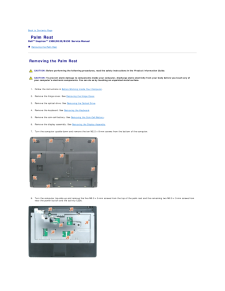
28 .Back to Contents Page Pa...Back to Contents Page Palm RestDell™ Inspiron™ 1300/B120/B130 Service Manual Removing the Palm Rest Removing the Palm Rest CAUTION: Before performing the following procedures, read the safety instructions in the Product Information Guide. CAUTION: To pr...
-
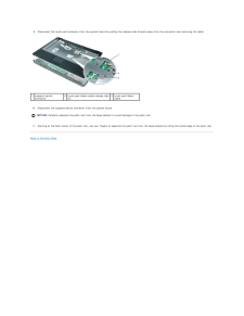
29 .9. Disconnect the touch p...9. Disconnect the touch pad connector from the system board by pulling the release tabs forward away from the connector and removing the cable.1 suspend switchconnector10.2 touch pad ribbon cable release tabs 3 touch pad ribbon(2)cable Disconnect the suspe...
-
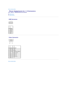
30 .Back to Contents Page Pi...Back to Contents Page Pinout Assignments for I/O ConnectorsDell™ Inspiron™ 1300/B120/B130 Service Manual USB Connector Video Connector USB Connector Pin Signal1USB5V+2USBP–3USBP+4GND Video Connector Pin Signal Pin Signal1CRT_R 95V+2CRT_G 10GND3CRT_...
-
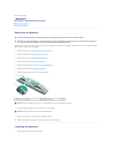
31 .Back to Contents Page Sp...Back to Contents Page SpeakersDell™ Inspiron™ 1300/B120/B130 Service Manual Removing the Speakers Installing the Speakers Removing the Speakers CAUTION: Before performing the following procedures, read the safety instructions in the Product Information...
-
32 .NOTICE: Ensure that the s...NOTICE: Ensure that the speaker cables are under or between their routing clips.NOTE: The speakers face out in the base plastics holders.NOTE: The right speaker cable is longer than the left speaker cable.2. Route the speaker cables under or between their ...
-
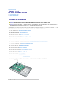
33 .Back to Contents Page Sy...Back to Contents Page System BoardDell™ Inspiron™ 1300/B120/B130 Service Manual Removing the System Board Installing the System Board Removing the System Board CAUTION: Before performing the following procedures, read the safety instructions in the Pro...
-
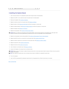
34 .1M2.5 x 5-mm screws (5)...1M2.5 x 5-mm screws (5) Installing the System Board1. Insert the video connector on the replacement system board through the side of the base plastics.2. Replace the five M2.5 x 5-mm screws that secure the system board to the base plastics.3. Reconnect...
-
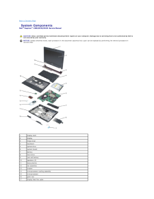
35 .Back to Contents Page Sy...Back to Contents Page System ComponentsDell™ Inspiron™ 1300/B120/B130 Service Manual CAUTION: Only a certified service technician should perform repairs on your computer. Damage due to servicing that is not authorized by Dell isnot covered by your warran...
-
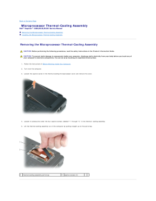
37 .Back to Contents Page Mi...Back to Contents Page Microprocessor Thermal-Cooling AssemblyDell™ Inspiron™ 1300/B120/B130 Service Manual Removing the Microprocessor Thermal-Cooling Assembly Installing the Microprocessor Thermal-Cooling Assembly Removing the Microprocessor Thermal-C...
-
38 .Installing the Microproc...Installing the Microprocessor Thermal-Cooling AssemblyNOTICE: Before you install the replacement microprocessor thermal-cooling assembly, remove the mylar that covers the thermal grease on theassembly.1. Lower the microprocessor thermal-cooling assembly i...
-
39 .Back to Contents PageDell...Back to Contents PageDell™ Inspiron™ 1300/B120/B130 Service ManualNOTE: A NOTE indicates important information that helps you make better use of your computer.NOTICE: A NOTICE indicates either potential damage to hardware or loss of data and tells you how...
-
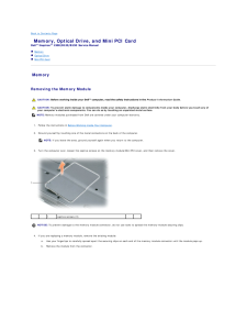
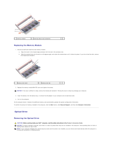
40 .Back to Contents Page Me...Back to Contents Page Memory, Optical Drive, and Mini PCI CardDell™ Inspiron™ 1300/B120/B130 Service Manual Memory Optical Drive Mini PCI Card Memory Removing the Memory Module CAUTION: Before working inside your Dell™ computer, read the safety instru...
-
41 .1memory module2securing c...1memory module2securing clips (2 per connector) Replacing the Memory Module1. Ground yourself and install the new memory module:a.b.1 Align the notch in the module edge connector with the tab in the connector slot. Slide the module firmly into the slot a...
-
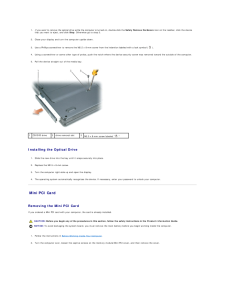
42 .If you want to remove th...If you want to remove the optical drive while the computer is turned on, double-click the Safely Remove Hardware icon on the taskbar, click the devicethat you want to eject, and click Stop. Otherwise go to step 2.1. Close your display and turn the compute...
-
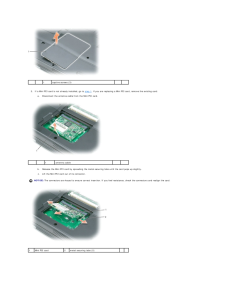
43 .1 3. If a Mini PCI car...1 3. If a Mini PCI card is not already installed, go to step 1. If you are replacing a Mini PCI card, remove the existing card:a. captive screws (3) Disconnect the antenna cable from the Mini PCI card.1antenna cable b. Release the Mini PCI card by spr...
-
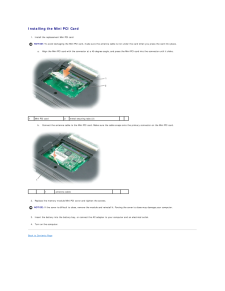
44 .Installing the Mini PCI C...Installing the Mini PCI Card1. Install the replacement Mini PCI card:NOTICE: To avoid damaging the Mini PCI card, make sure the antenna cable is not under the card when you press the card into place.a.1 Align the Mini PCI card with the connector at a 45-de...
