
XPS M1210の取扱説明書・マニュアル [全44ページ 1.63MB]


6


3 / 44 ページ
3 / 44 ページ


現在のページURL
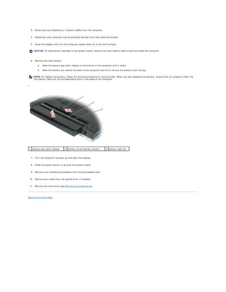
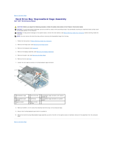
3. Disconnect any telephone or network cables from the computer.4. Disconnect your computer and all attached devices from their electrical outlets.5. Close the display and turn the computer upside down on a flat work surface.NOTICE: To help prevent damage to the system board, remove the main battery before working inside the computer.6. Remove the main battery:a. Slide the battery-bay latch release on the bottom of the computer until it clicks.b. Slide the battery out toward the back of the computer and lift to remove the battery from the bay.NOTE: To replace the battery, follow the removal procedure in reverse order. When you are replacing the battery, ensure that you properly insert thetwo battery tabs into the corresponding slots in the base of the computer.I1battery-bay latch release2battery (9-cell battery shown)7. Turn the computer top-side up and open the display.8. Press the power button to ground the system board.9. Remove any installed ExpressCard from the ExpressCard slot.10. Remove any media from the optical drive, if installed.11. Remove the hard drive (see Removing the Hard Drive).Back to Contents Page 3battery tabs (2)
参考になったと評価  15人が参考になったと評価しています。
その他の取扱説明書

1334 view

639 view
このマニュアルの目次
-
1 .Dell™ XPS™ M1210 Service ...Dell™ XPS™ M1210 Service Manual Before You BeginCoin-Cell BatteryOptical DrivePalm RestHard DriveModemMemory Module(s)Processor ModuleHinge CoverFanKeyboardThermal-Cooling AssemblyMini-CardsHard Drive Bay/ExpressCard Cage AssemblyInternal Card With Bluetoo...
-
2 .Back to Contents Page Be...Back to Contents Page Before You BeginDell™ XPS™ M1210 Service Manual Recommended Tools Turning Off Your Computer Before Working Inside Your ComputerThis section provides procedures for removing and installing the components in your computer. Unless ot...
-
3 .3. Disconnect any telepho...3. Disconnect any telephone or network cables from the computer.4. Disconnect your computer and all attached devices from their electrical outlets.5. Close the display and turn the computer upside down on a flat work surface.NOTICE: To help prevent damage ...
-
4 .Back to Contents Page In...Back to Contents Page Internal Card With Bluetooth® Wireless TechnologyDell™ XPS™ M1210 Service Manual CAUTION: Before you begin the following procedure, follow the safety instructions in the Product Information Guide.NOTICE: To avoid electrostatic discha...
-
5 .Back to Contents Page Ca...Back to Contents Page Camera (Optional)Dell™ XPS™ M1210 Service Manual Removing the Camera Replacing the Camera Removing the Camera CAUTION: Before you begin the following procedure, follow the safety instructions in the Product Information Guide.NOTICE...
-
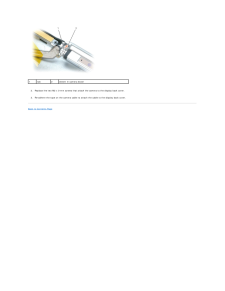
6 .1tab2detent in camera bez...1tab2detent in camera bezel2. Replace the two M2 x 3-mm screws that attach the camera to the display back cover.3. Re-adhere the tape on the camera cable to attach the cable to the display back cover.Back to Contents Page
-
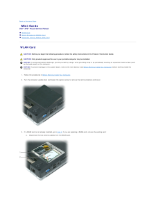
7 .Back to Contents Page Mi...Back to Contents Page Mini-CardsDell™ XPS™ M1210 Service Manual WLAN Card Mobile Broadband (WWAN) Card Subscriber Identity Module (SIM) Card WLAN Card CAUTION: Before you begin the following procedure, follow the safety instructions in the Product Info...
-
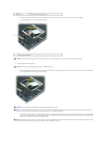
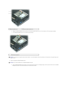
8 .1WLAN card2antenna cable ...1WLAN card2antenna cable connectors (2)b. Release the WLAN card by pushing the metal securing tabs toward the back of the computer until the card pops up slightly.c. Lift the WLAN card out of its system board connector.1metal securing tabs (2)NOTICE: The c...
-
9 .1antenna cable connectors...1antenna cable connectors (2)5.6.2triangles (2) Replace the communications card cover. If the WLAN card you just replaced is being installed in this computer for the first time, see "Using Networks" and "Drivers" in the Owner's Manual foryour computer for ...
-
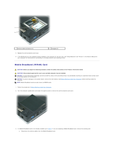
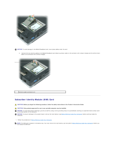
10 .1Mobile Broadband card2an...1Mobile Broadband card2antenna cable connectors (2)b. Release the Mobile Broadband card by pushing the metal securing tabs toward the front of the computer until the card pops up slightly.c. Lift the Mobile Broadband card out of its system board connector....
-
11 .NOTICE: To avoid damage t...NOTICE: To avoid damage to the Mobile Broadband card, never place cables under the card.b.1 Connect the two antenna cables to the Mobile Broadband card (black [auxiliary] cable to the connector with a black triangle and the white [main]cable to the connect...
-
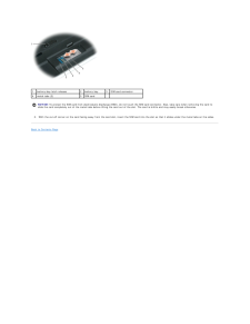
12 .1battery-bay latch releas...1battery-bay latch release2battery bay3SIM card connector4metal tabs (2)5SIM card NOTICE: To protect the SIM card from electrostatic discharge (ESD), do not touch the SIM card connector. Also, take care when removing the card toslide the card completely o...
-
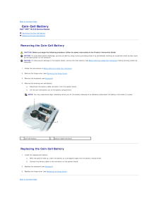
13 .Back to Contents Page Co...Back to Contents Page Coin-Cell BatteryDell™ XPS™ M1210 Service Manual Removing the Coin-Cell Battery Replacing the Coin-Cell Battery Removing the Coin-Cell Battery CAUTION: Before you begin the following procedure, follow the safety instructions in the...
-
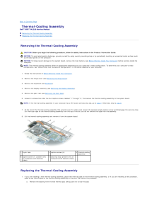
14 .Back to Contents Page Th...Back to Contents Page Thermal-Cooling AssemblyDell™ XPS™ M1210 Service Manual Removing the Thermal-Cooling Assembly Replacing the Thermal-Cooling Assembly Removing the Thermal-Cooling Assembly CAUTION: Before you begin the following procedure, follow th...
-
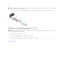
15 .NOTE: You can place the n...NOTE: You can place the new thermal pads directly on any existing thermal pads already installed on the thermal-cooling assembly. It is not necessaryto remove an existing pad or to clean the surface.b.1 On the underside of the thermal-cooling assembly, pla...
-
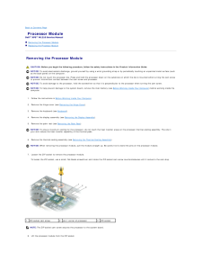
16 .Back to Contents Page Pr...Back to Contents Page Processor ModuleDell™ XPS™ M1210 Service Manual Removing the Processor Module Replacing the Processor Module Removing the Processor Module CAUTION: Before you begin the following procedure, follow the safety instructions in the Pro...
-
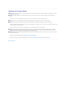
17 .Replacing the Processor ...Replacing the Processor ModuleNOTICE: Ensure that the cam lock is in the fully open position before seating the processor module. Seating the processor module properly in the ZIFsocket does not require force.NOTICE: A processor module that is not properly...
-
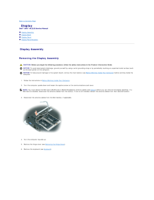
18 .Back to Contents Page Di...Back to Contents Page DisplayDell™ XPS™ M1210 Service Manual Display Assembly Display Bezel Display Panel Display-Panel Brackets Display Assembly Removing the Display Assembly CAUTION: Before you begin the following procedure, follow the safety instru...
-
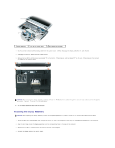
19 .1display assembly2pull-ta...1display assembly2pull-tab on display cable3Mini-Card antenna cables7. Use the pull-tab to disconnect the display cable from the system board, and then disengage the display cable from its cable channel.8. Disengage the antenna cables from their cable chan...
-
20 .5.Reroute the display cab...5.Reroute the display cable in the cable channel.6. Reroute the antenna cables in their cable channel.7. Replace the hinge cover (see Replacing the Hinge Cover).8.9. If any Mini-Cards are installed, connect the antenna cables to the card(s) (see Mini-Cards...
-
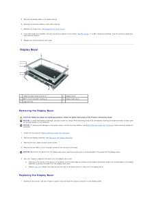
21 .NOTE: To facilitate repla...NOTE: To facilitate replacement of the display bezel, ensure that the camera connector is tucked in place beside the display panel before you snap thebezel into place.2. Replace the four M2.5 x 5-mm screws on the corners of the bezel.3. Replace the four ru...
-
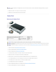
22 .a. Use the pull-tab to di...a. Use the pull-tab to disconnect the bottom flex-cable connector from the inverter connector.b. Lift the tape, if present, as necessary to pull the top flex-cable connector away from the display connector.c. If an optional camera is present on the compute...
-
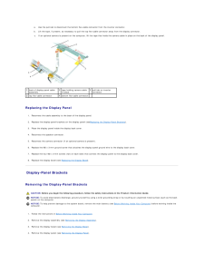
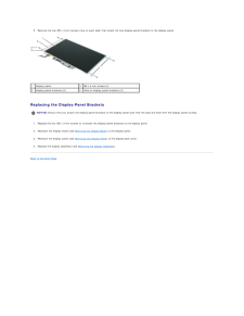
23 .5.Remove the four M2 x 3-...5.Remove the four M2 x 3-mm screws (two on each side) that attach the two display-panel brackets to the display panel.1display panel3M2 x 3-mm screws (4)2display-panel brackets (2)4tabs on display-panel brackets (4) Replacing the Display-Panel BracketsNOTI...
-
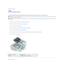
24 .Back to Contents Page Fa...Back to Contents Page FanDell™ XPS™ M1210 Service Manual CAUTION: Before you begin the following procedure, follow the safety instructions in the Product Information Guide.NOTICE: To avoid electrostatic discharge, ground yourself by using a wrist groundin...
-
25 .Back to Contents Page Fl...Back to Contents Page Flashing the BIOSDell™ XPS™ M1210 Service ManualNOTICE: Plug the AC adapter into a known good power source to prevent a loss of power. Failure to do so may cause system damage.1. Ensure that the AC adapter is plugged in and that the ...
-
26 .Back to Contents Page Ha...Back to Contents Page Hard Drive Bay/ExpressCard Cage AssemblyDell™ XPS™ M1210 Service Manual CAUTION: Before you begin the following procedure, follow the safety instructions in the Product Information Guide.NOTICE: To avoid electrostatic discharge, grou...
-
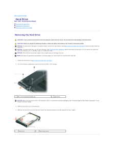
27 .Back to Contents Page Ha...Back to Contents Page Hard DriveDell™ XPS™ M1210 Service Manual Removing the Hard Drive Replacing the Hard Drive Returning a Hard Drive to Dell Removing the Hard Drive CAUTION: If you remove the hard drive from the computer when the drive is hot, do no...
-
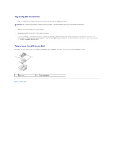
28 .Replacing the Hard Drive...Replacing the Hard Drive1. Place the new drive in the hard drive carrier from which you removed the original hard drive.NOTICE: Use firm and even pressure to slide the drive into place. If you use excessive force, you may damage the connector.2. Slide the...
-
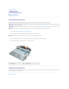
29 .Back to Contents Page Hi...Back to Contents Page Hinge CoverDell™ XPS™ M1210 Service Manual Removing the Hinge Cover Replacing the Hinge Cover Removing the Hinge Cover CAUTION: Before you begin the following procedure, follow the safety instructions in the Product Information Gui...
-
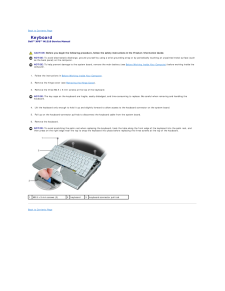
30 .Back to Contents Page Ke...Back to Contents Page KeyboardDell™ XPS™ M1210 Service Manual CAUTION: Before you begin the following procedure, follow the safety instructions in the Product Information Guide.NOTICE: To avoid electrostatic discharge, ground yourself by using a wrist gro...
-
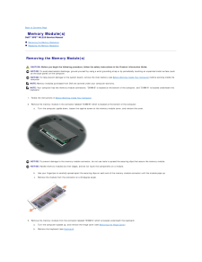
31 .Back to Contents Page Me...Back to Contents Page Memory Module(s)Dell™ XPS™ M1210 Service Manual Removing the Memory Module(s) Replacing the Memory Module(s) Removing the Memory Module(s) CAUTION: Before you begin the following procedure, follow the safety instructions in the Pro...
-
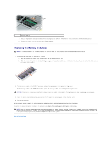
32 .1securing clips (2)c. Use...1securing clips (2)c. Use your fingertips to carefully spread apart the securing clips on each end of the memory module connector until the module pops up.d. Remove the module from the connector at a 45-degree angle. Replacing the Memory Module(s)NOTE: If ...
-
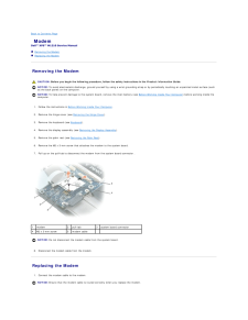
33 .Back to Contents Page Mo...Back to Contents Page ModemDell™ XPS™ M1210 Service Manual Removing the Modem Replacing the Modem Removing the Modem CAUTION: Before you begin the following procedure, follow the safety instructions in the Product Information Guide.NOTICE: To avoid elec...
-
34 .2. Connect the modem to t...2. Connect the modem to the system board.Align the connector on the bottom of the modem with the modem connector on the system board, and press down on the end of the modem labeled"PRESS HERE."3. Replace the M2 x 3-mm screw.Back to Contents Page
-
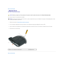
35 .Back to Contents Page Op...Back to Contents Page Optical DriveDell™ XPS™ M1210 Service Manual CAUTION: Before you begin any of the procedures in this section, follow the safety instructions in the Product Information Guide.Your computer ships with a fixed optical drive installed.NO...
-
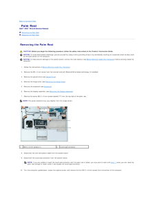
36 .Back to Contents Page Pa...Back to Contents Page Palm RestDell™ XPS™ M1210 Service Manual Removing the Palm Rest Replacing the Palm Rest Removing the Palm Rest CAUTION: Before you begin the following procedure, follow the safety instructions in the Product Information Guide.NOTIC...
-
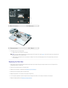
37 .1M2.5 x 8-mm screws (4)1t...1M2.5 x 8-mm screws (4)1touch-pad connector11.2captive screw2tabs (4) Lift the palm rest from the computer base:a. Raise the palm rest at the back of the computer.NOTE: If you were unable to disconnect the touch-pad connector with the palm rest in place (s...
-
38 .8.Replace the keyboard (s...8.Replace the keyboard (see Keyboard).9. Replace the hinge cover (see Replacing the Hinge Cover).Back to Contents Page
-
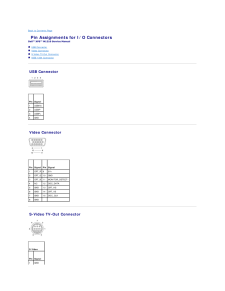
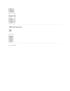
39 .Back to Contents Page Pi...Back to Contents Page Pin Assignments for I/O ConnectorsDell™ XPS™ M1210 Service Manual USB Connector Video Connector S-Video TV-Out Connector IEEE 1394 Connector USB Connector Pin Signal1USB5V+2USBP–3USBP+4GND Video Connector Pin Signal Pin Signa...
-
40 .2GND3DLUMA-L4DCRMA-L Comp...2GND3DLUMA-L4DCRMA-L Composite Video PinSignal5NC6DCMPS-L7GND IEEE 1394 Connector Pin Signal1TPB–2TPB+3TPA–4TPA+Back to Contents Page
-
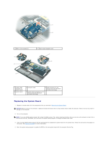
41 .Back to Contents Page Sy...Back to Contents Page System BoardDell™ XPS™ M1210 Service Manual Removing the System Board Replacing the System Board Removing the System Board CAUTION: Before you begin the following procedure, follow the safety instructions in the Product Information...
-
42 .1M2.5 x 5-mm screws (2)2i...1M2.5 x 5-mm screws (2)2input/output daughter card1 modem cableconnector onsystem board3 computer base5 cable connector for theinternal card with Bluetoothwireless technology2 system board4 system board connector for theinternal card with Bluetoothwireless...
-
44 .Back to Contents PageDell...Back to Contents PageDell™ XPS™ M1210 Service ManualNOTE: A NOTE indicates important information that helps you make better use of your computer.NOTICE: A NOTICE indicates either potential damage to hardware or loss of data and tells you how to avoid the p...
