
Vostro 1540の取扱説明書・マニュアル [全86ページ 7.59MB]


4


1 / 86 ページ
1 / 86 ページ


現在のページURL
Dell Vostro 1540/1550Owner's ManualRegulatory Model P18FRegulatory Type P18F001,P18F002
参考になったと評価  7人が参考になったと評価しています。
その他の取扱説明書

1736 view

28388 view

805 view
このマニュアルの目次
-
1 .Dell Vostro 1540/1550Owne...Dell Vostro 1540/1550Owner's ManualRegulatory Model P18FRegulatory Type P18F001,P18F002
-
2 .Notes, Cautions, and Warn...Notes, Cautions, and WarningsNOTE: A NOTE indicates important information that helps you make better use of yourcomputer.CAUTION: A CAUTION indicates potential damage to hardware or loss of data ifinstructions are not followed.WARNING: A WARNING indicates...
-
3 .ContentsNotes, Cautions, ...ContentsNotes, Cautions, and Warnings .................................................................. 21 Working on Your Computer ...................................................................... 7Before Working Inside Your Computer ..................
-
4 .9 Removing The Power Butt...9 Removing The Power Button Board ...................................................... 27Installing The Power Button Board ................................................................................. 2810 Removing The Hard Drive .......................
-
5 .21 Removing The Display B...21 Removing The Display Bezel ................................................................ 59Installing The Display Bezel ............................................................................................ 6022 Removing The Camera ...............
-
6 .6 ページ目のマニュアル
-
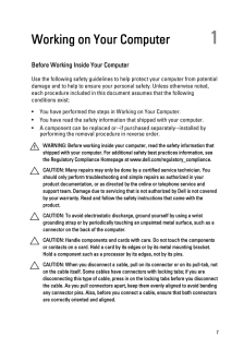
7 .Working on Your Computer ...Working on Your Computer 1Before Working Inside Your ComputerUse the following safety guidelines to help protect your computer from potentialdamage and to help to ensure your personal safety. Unless otherwise noted,each procedure included in this document ...
-
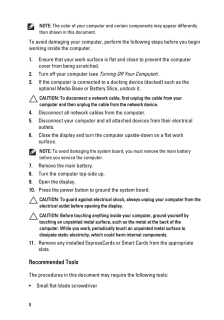
8 .NOTE: The color of your ...NOTE: The color of your computer and certain components may appear differentlythan shown in this document.To avoid damaging your computer, perform the following steps before you beginworking inside the computer.1. Ensure that your work surface is flat and...
-
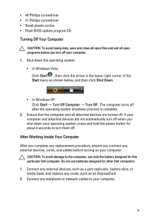
9 .* #0 Phillips screwdriver...* #0 Phillips screwdriver* #1 Phillips screwdriver* Small plastic scribe* Flash BIOS update program CDTurning Off Your ComputerCAUTION: To avoid losing data, save and close all open files and exit all openprograms before you turn off your computer.1. Shut ...
-
10 .CAUTION: To connect a net...CAUTION: To connect a network cable, first plug the cable into the network deviceand then plug it into the computer.3. Replace the battery.4. Connect your computer and all attached devices to their electrical outlets.5. Turn on your computer.10
-
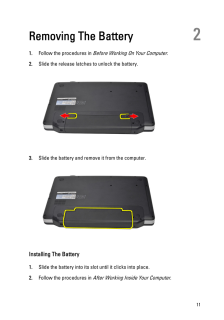
11 .Removing The Battery 21. ...Removing The Battery 21. Follow the procedures in Before Working On Your Computer .2. Slide the release latches to unlock the battery.3. Slide the battery and remove it from the computer.Installing The Battery1. Slide the battery into its slot until it cli...
-
12 .12 ページ目のマニュアル
-
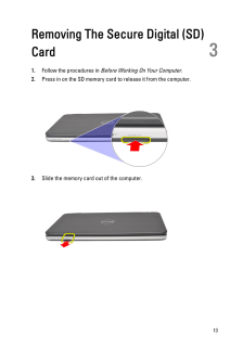
13 .Removing The Secure Digit...Removing The Secure Digital (SD)Card 31. Follow the procedures in Before Working On Your Computer .2. Press in on the SD memory card to release it from the computer.3. Slide the memory card out of the computer.13
-
14 .Installing The Secure Dig...Installing The Secure Digital (SD) Card1. Push the memory card into the compartment until it is fully engaged with aclick sound.2. Follow the procedures in After Working Inside Your Computer .14
-
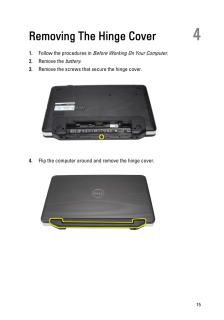
15 .Removing The Hinge Cover ...Removing The Hinge Cover 41. Follow the procedures in Before Working On Your Computer .2. Remove the battery .3. Remove the screws that secure the hinge cover.4. Flip the computer around and remove the hinge cover.15
-
16 .Installing The Hinge Cove...Installing The Hinge Cover1. Install the hinge cover and press on it to secure its connection to thecomputer.2. Flip the computer around and install the screws that secure the hingecover.3. Install the battery .4. Follow the procedures in After Working Ins...
-
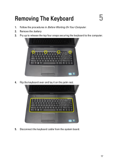
17 .Removing The Keyboard 51....Removing The Keyboard 51. Follow the procedures in Before Working On Your Computer .2. Remove the battery .3. Pry up to release the top four snaps securing the keyboard to the computer.4. Flip the keyboard over and lay it on the palm rest.5. Disconnect the...
-
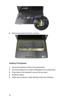
18 .6. Remove the keyboard fr...6. Remove the keyboard from the computer.Installing The Keyboard1. Connect the keyboard cable to the system board.2. Insert the keyboard at an angle of 30 degrees to its compartment.3. Press down on the keyboard to secure the top snaps.4. Install the batte...
-
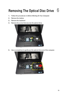
19 .Removing The Optical Disc...Removing The Optical Disc Drive 61. Follow the procedures in Before Working On Your Computer .2. Remove the battery .3. Remove the keyboard .4. Remove the screw that secures the optical drive.5. Use a screwdriver to gently pry the optical drive out of the ...
-
20 .Installing The Optical Di...Installing The Optical Disc Drive1. Slide the optical drive into the compartment on the left side of the chassis.2. Tighten the screw to secure the optical drive to the computer.3. Install the keyboard .4. Install the battery .5. Follow the procedures in A...
-
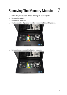
21 .Removing The Memory Modul...Removing The Memory Module 71. Follow the procedures in Before Working On Your Computer .2. Remove the battery .3. Remove the keyboard .4. Pry the retention clips away from the memory module until it pops up.5. Remove the memory module from the computer.21
-
22 .Installing The Memory Mod...Installing The Memory Module1. Insert the memory module into the memory socket.2. Press down on the memory module until the retention clips secure thememory module in place.3. Install the keyboard .4. Install the battery .5. Follow the procedures in After ...
-
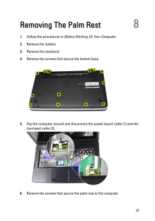
23 .Removing The Palm Rest 81...Removing The Palm Rest 81. Follow the procedures in Before Working On Your Computer .2. Remove the battery .3. Remove the keyboard .4. Remove the screws that secure the bottom base.5. Flip the computer around and disconnect the power board cable (1) and th...
-
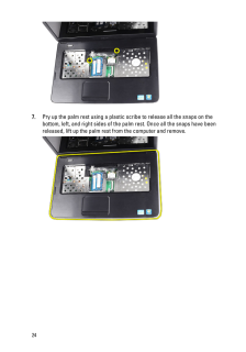
24 .7. Pry up the palm rest u...7. Pry up the palm rest using a plastic scribe to release all the snaps on thebottom, left, and right sides of the palm rest. Once all the snaps have beenreleased, lift up the palm rest from the computer and remove.24
-
25 .Installing The Palm Rest1...Installing The Palm Rest1. Insert the palm rest towards the display screen at a 30-degree angle.2. Align and adjust the palm rest into position before pressing it down tosecure all the snaps.3. Connect the power board cable and touchpad cable to their resp...
-
26 .26 ページ目のマニュアル
-
27 .Removing The Power Button...Removing The Power Button Board91. Follow the procedures in Before Working On Your Computer .2. Remove the battery .3. Remove the keyboard .4. Remove the palm rest .5. Peel the power button board cable from the adhesive affixing it to the palmrest.6. Flip ...
-
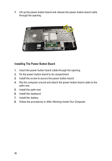
28 .7. Lift up the power butt...7. Lift up the power button board and release the power button board cablethrough the opening.Installing The Power Button Board1. Insert the power button board cable through the opening.2. Fix the power button board to its compartment.3. Install the screw ...
-
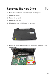
29 .Removing The Hard Drive 1Removing The Hard Drive 101. Follow the procedures in Before Working On Your Computer .2. Remove the battery .3. Remove the keyboard .4. Remove the palm rest .5. Slide the hard drive and lift it out of the computer.6. Remove the screws that secure the hard...
-
30 .Installing The Hard Drive...Installing The Hard Drive1. Install the hard drive bracket to the hard drive.2. Tighten the screws that secure the hard drive bracket.3. Place the hard drive in its compartment and slide it towards the SATAconnector to secure it to the system board.4. Inst...
-
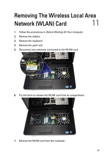
31 .Removing The Wireless Loc...Removing The Wireless Local AreaNetwork (WLAN) Card 111. Follow the procedures in Before Working On Your Computer .2. Remove the battery .3. Remove the keyboard .4. Remove the palm rest .5. Disconnect any antennae connected to the WLAN card.6. Pry the latc...
-
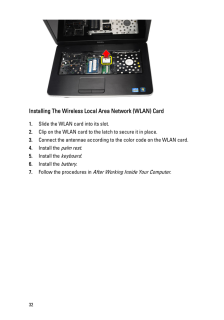
32 .Installing The Wireless L...Installing The Wireless Local Area Network (WLAN) Card1. Slide the WLAN card into its slot.2. Clip on the WLAN card to the latch to secure it in place.3. Connect the antennae according to the color code on the WLAN card.4. Install the palm rest .5. Install...
-
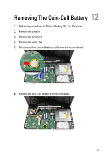
33 .Removing The Coin-Cell Ba...Removing The Coin-Cell Battery 121. Follow the procedures in Before Working On Your Computer .2. Remove the battery .3. Remove the keyboard .4. Remove the palm rest .5. Disconnect the coin-cell battery cable from the system board.6. Remove the coin-cell ba...
-
34 .Installing The Coin-Cell ...Installing The Coin-Cell Battery1. Install the coin-cell battery to the coin-cell battery compartment.2. Connect the coin-cell battery cable to the system board.3. Install the palm rest .4. Install the keyboard .5. Install the battery .6. Follow the proced...
-
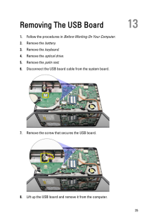
35 .Removing The USB Board 13...Removing The USB Board 131. Follow the procedures in Before Working On Your Computer .2. Remove the battery .3. Remove the keyboard .4. Remove the optical drive .5. Remove the palm rest .6. Disconnect the USB board cable from the system board.7. Remove the...
-
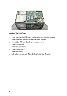
36 .Installing The USB Board1...Installing The USB Board1. Insert and align the USB board into its compartment on the computer.2. Install the screw that secures the USB board in place.3. Connect the USB board cable to the system board.4. Install the palm rest .5. Install the optical driv...
-
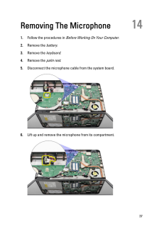
37 .Removing The Microphone 1...Removing The Microphone 141. Follow the procedures in Before Working On Your Computer .2. Remove the battery .3. Remove the keyboard .4. Remove the palm rest .5. Disconnect the microphone cable from the system board.6. Lift up and remove the microphone fro...
-
38 .Installing The Microphone...Installing The Microphone1. Insert and align the microphone into its compartment.2. Connect the microphone cable to the system board.3. Install the palm rest .4. Install the keyboard .5. Install the battery .6. Follow the procedures in After Working Inside...
-
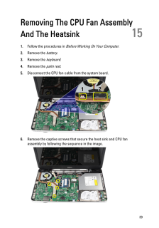
39 .Removing The CPU Fan Asse...Removing The CPU Fan AssemblyAnd The Heatsink 151. Follow the procedures in Before Working On Your Computer .2. Remove the battery .3. Remove the keyboard .4. Remove the palm rest .5. Disconnect the CPU fan cable from the system board.6. Remove the captive...
-
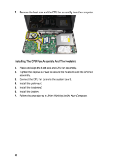
40 .7. Remove the heat sink a...7. Remove the heat sink and the CPU fan assembly from the computer.Installing The CPU Fan Assembly And The Heatsink1. Place and align the heat sink and CPU fan assembly.2. Tighten the captive screws to secure the heat sink and the CPU fanassembly.3. Connec...
-
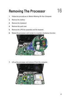
41 .Removing The Processor 16...Removing The Processor 161. Follow the procedures in Before Working On Your Computer .2. Remove the battery .3. Remove the keyboard .4. Remove the palm rest .5. Remove the CPU fan assembly and the heatsink .6. Rotate the processor-cam screw in a counter-cl...
-
42 .Installing The Processor1...Installing The Processor1. Insert the processor into the processor socket. Ensure the processor isproperly seated.2. Tighten the cam-screw in a clockwise direction to the locked position.3. Install the CPU fan assembly and the heatsink .4. Install the palm...
-
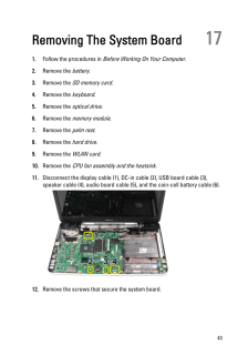
43 .Removing The System Board...Removing The System Board 171. Follow the procedures in Before Working On Your Computer .2. Remove the battery .3. Remove the SD memory card .4. Remove the keyboard .5. Remove the optical drive .6. Remove the memory module .7. Remove the palm rest .8. Remo...
-
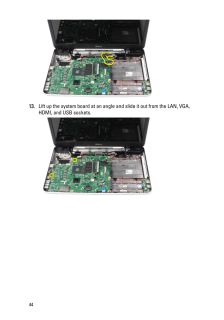
44 .13. Lift up the system bo...13. Lift up the system board at an angle and slide it out from the LAN, VGA,HDMI, and USB sockets.44
-
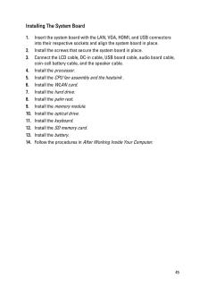
45 .Installing The System Boa...Installing The System Board1. Insert the system board with the LAN, VGA, HDMI, and USB connectorsinto their respective sockets and align the system board in place.2. Install the screws that secure the system board in place.3. Connect the LCD cable, DC-in c...
-
46 .46 ページ目のマニュアル
-
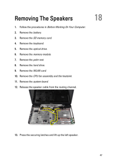
47 .Removing The Speakers 181...Removing The Speakers 181. Follow the procedures in Before Working On Your Computer .2. Remove the battery .3. Remove the SD memory card .4. Remove the keyboard .5. Remove the optical drive .6. Remove the memory module .7. Remove the palm rest .8. Remove t...
-
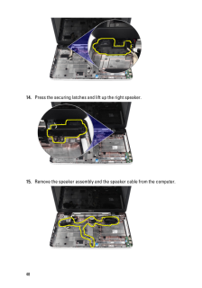
48 .14. Press the securing la...14. Press the securing latches and lift up the right speaker.15. Remove the speaker assembly and the speaker cable from the computer.48
-
49 .Installing The Speakers1....Installing The Speakers1. Insert and attach the left and right speakers into their respectivecompartments.2. Align and route the speaker cable to the chassis.3. Install the system board .4. Install the processor .5. Install the CPU fan assembly and the hea...
-
50 .50 ページ目のマニュアル
-
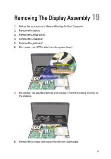
51 .Removing The Display Asse...Removing The Display Assembly 191. Follow the procedures in Before Working On Your Computer .2. Remove the battery .3. Remove the hinge cover .4. Remove the keyboard .5. Remove the palm rest .6. Disconnect the LVDS cable from the system board.7. Disconnect...
-
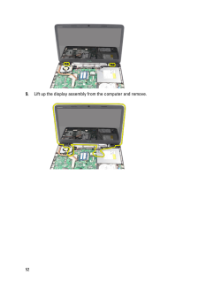
53 .Installing The Display As...Installing The Display Assembly1. Insert the display assembly hinges into their holders.2. Install the screws that secure both the hinges in place.3. Connect the LVDS cable to the system board.4. Align the WLAN antennae routing cable to its holder and conn...
-
54 .54 ページ目のマニュアル
-
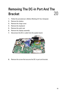
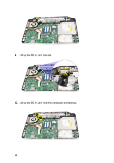
55 .Removing The DC-in Port A...Removing The DC-in Port And TheBracket 201. Follow the procedures in Before Working On Your Computer .2. Remove the battery .3. Remove the hinge cover .4. Remove the keyboard .5. Remove the palm rest .6. Remove the display assembly7. Disconnect the DC-in c...
-
56 .9. Lift up the DC-in port...9. Lift up the DC-in port bracket.10. Lift up the DC-in port from the computer and remove.56
-
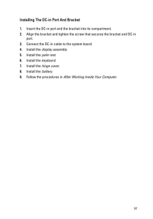
57 .Installing The DC-in Port...Installing The DC-in Port And Bracket1. Insert the DC-in port and the bracket into its compartment.2. Align the bracket and tighten the screw that secures the bracket and DC-inport.3. Connect the DC-in cable to the system board.4. Install the display assem...
-
58 .58 ページ目のマニュアル
-
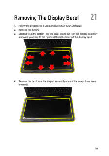
59 .Removing The Display Beze...Removing The Display Bezel 211. Follow the procedures in Before Working On Your Computer .2. Remove the battery .3. Starting from the bottom , pry the bezel inside out from the display assemblyand work your way to the right and the left corners of the disp...
-
60 .Installing The Display Be...Installing The Display Bezel1. Align the display bezel in line with the top cover.2. Starting from the bottom edge, press downward on the display bezel toengage the tabs.3. Install the battery .4. Follow the procedures in After Working Inside Your Computer...
-
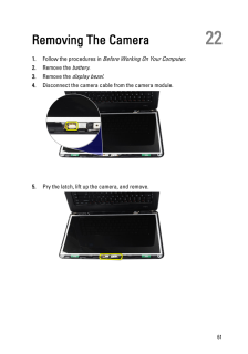
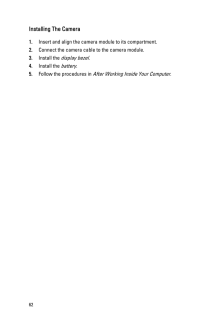
61 .Removing The Camera 221. ...Removing The Camera 221. Follow the procedures in Before Working On Your Computer .2. Remove the battery .3. Remove the display bezel .4. Disconnect the camera cable from the camera module.5. Pry the latch, lift up the camera, and remove.61
-
62 .Installing The Camera1. I...Installing The Camera1. Insert and align the camera module to its compartment.2. Connect the camera cable to the camera module.3. Install the display bezel .4. Install the battery .5. Follow the procedures in After Working Inside Your Computer .62
-
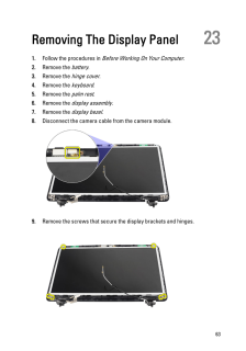
63 .Removing The Display Pane...Removing The Display Panel 231. Follow the procedures in Before Working On Your Computer .2. Remove the battery .3. Remove the hinge cover .4. Remove the keyboard .5. Remove the palm rest .6. Remove the display assembly .7. Remove the display bezel .8. Dis...
-
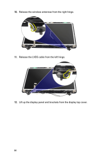
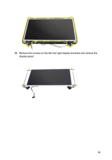
64 .10. Release the wireless ...10. Release the wireless antennae from the right hinge.11. Release the LVDS cable from the left hinge.12. Lift up the display panel and brackets from the display top cover.64
-
65 .13. Remove the screws on ...13. Remove the screws on the left and right display brackets and remove thedisplay panel.65
-
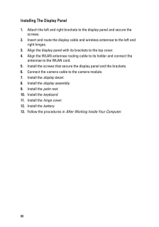
66 .Installing The Display Pa...Installing The Display Panel1. Attach the left and right brackets to the display panel and secure thescrews.2. Insert and route the display cable and wireless antennae to the left andright hinges.3. Align the display panel with its brackets to the top cove...
-
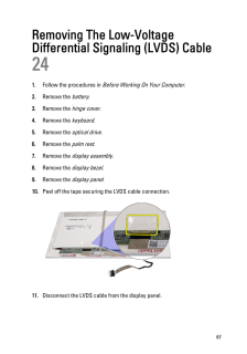
67 .Removing The Low-VoltageD...Removing The Low-VoltageDifferential Signaling (LVDS) Cable241. Follow the procedures in Before Working On Your Computer .2. Remove the battery .3. Remove the hinge cover .4. Remove the keyboard .5. Remove the optical drive .6. Remove the palm rest .7. Rem...
-
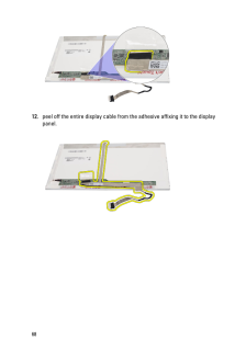
68 .12. peel off the entire d...12. peel off the entire display cable from the adhesive affixing it to the displaypanel.68
-
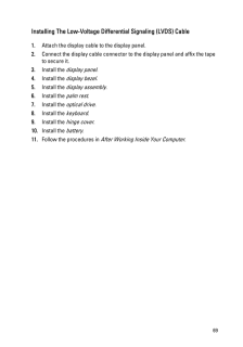
69 .Installing The Low-Voltag...Installing The Low-Voltage Differential Signaling (LVDS) Cable1. Attach the display cable to the display panel.2. Connect the display cable connector to the display panel and affix the tapeto secure it.3. Install the display panel .4. Install the display b...
-
70 .70 ページ目のマニュアル
-
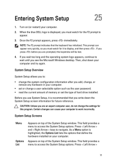
71 .Entering System Setup 251...Entering System Setup 251. Turn on (or restart) your computer.2. When the blue DELL logo is displayed, you must watch for the F2 prompt toappear.3. Once the F2 prompt appears, press
immediately.NOTE: The F2 prompt indicates that the keyboard has init... -
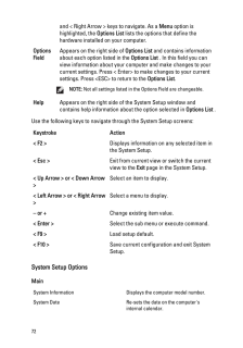
72 .and < Right Arrow > keys ...and < Right Arrow > keys to navigate. As a Menu option ishighlighted, the Options List lists the options that define thehardware installed on your computer.OptionsFieldAppears on the right side of Options List and contains informationabout each optio...
-
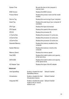
73 .System Time Re-sets the t...System Time Re-sets the time on the computer'sinternal clock.BIOS Version Displays the BIOS revision.Product Name Displays the product name and the modelnumber.Service Tag Displays the service tag of your computer.Asset Tag Displays the asset tag of your c...
-
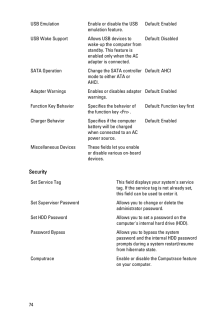
74 .USB Emulation Enable or d...USB Emulation Enable or disable the USBemulation feature.Default: EnabledUSB Wake Support Allows USB devices towake-up the computer fromstandby. This feature isenabled only when the ACadapter is connected.Default: DisabledSATA Operation Change the SATA con...
-
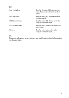
75 .BootBoot Priority Order S...BootBoot Priority Order Specifies the order of different devices inwhich the computer will boot through atstart up.Hard Disk Drives Specifies which hard drive the computercan boot through.USB Storage Device Specifies which USB storage device thecomputer ca...
-
76 .76 ページ目のマニュアル
-
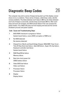
77 .Diagnostic Beep Codes 26T...Diagnostic Beep Codes 26The computer may emit a series of beeps during start-up if the display cannotshow errors or problems. These series of beeps, called beep codes, identifyvarious problems. The delay between each beep is 300 ms, the delay betweeneach s...
-
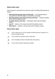
78 .Battery Status LightsIf t...Battery Status LightsIf the computer is connected to an electrical outlet, the battery light operates asfollows:*Alternately blinking amber light and white light - An unauthenticated orunsupported non-Dell AC adapter is attached to your laptop.*Alternatel...
-
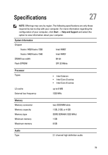
79 .Specifications 27NOTE: O...Specifications 27NOTE: Offerings may vary by region. The following specifications are only thoserequired by law to ship with your computer. For more information regarding theconfiguration of your computer, click Start → Help and Support and select theo...
-
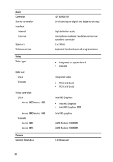
80 .AudioController IDT 92HD8...AudioController IDT 92HD87B1Stereo conversion 24-bit (analog-to-digital and digital-to-analog)Interface:Internal high definition audioExternal microphone-in/stereo headphones/externalspeakers connectorSpeakers 2 x 2 WattVolume controls keyboard function ke...
-
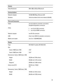
81 .CameraVideo Resolution 64CameraVideo Resolution 640 x 480 at 30 fps (Maximum)CommunicationsNetwork adapter 10/100/1000 Mbps Ethernet LANWireless internal wireless local area network (WLAN)Ports and ConnectorsAudio one microphone connector; one stereoheadphone/speakers connectorVid...
-
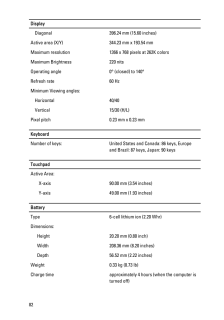
82 .DisplayDiagonal 396.24 mm...DisplayDiagonal 396.24 mm (15.60 inches)Active area (X/Y) 344.23 mm x 193.54 mmMaximum resolution 1366 x 768 pixels at 262K colorsMaximum Brightness 220 nitsOperating angle 0 (closed) to 140Refresh rate 60 HzMinimum Viewing angles:Horizontal 40/40Vertical ...
-
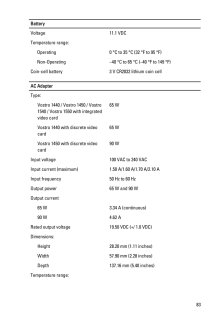
83 .BatteryVoltage 11.1 VDCTe...BatteryVoltage 11.1 VDCTemperature range:Operating 0 C to 35 C (32 F to 95 F)Non-Operating -40 C to 65 C (-40 F to 149 F)Coin-cell battery 3 V CR2032 lithium coin cellAC AdapterType:Vostro 1440 / Vostro 1450 / Vostro1540 / Vostro 1550 with integratedvideo ...
-
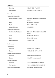
84 .AC AdapterOperating 0 C t...AC AdapterOperating 0 C to 40 C (32 F to 104 F)Non-Operating -40 C to 70 C (-40 F to 158 F)PhysicalVostro 1440 / Vostro 1450:Height (with a WLED panel) 31.50 mm to 34.70 mm (1.24 inches to 1.36inches)Width 342.00 mm (13.46 inches)Depth 244 mm (9.60 inches)...
-
85 .Contacting Dell 28Contact...Contacting Dell 28Contacting DellNOTE: If you do not have an active Internet connection, you can find contactinformation on your purchase invoice, packing slip, bill, or Dell product catalog.Dell provides several online and telephone-based support and ser...
-
86 .86 ページ目のマニュアル
