
Inspiron 1150の取扱説明書・マニュアル [全38ページ 1.36MB]


4


1 / 38 ページ
1 / 38 ページ


現在のページURL
Dell™ Inspiron™ 1150 Service ManualBefore You BeginSystem ComponentsMemory, CD or DVD Drive, Modem, and Mini PCI CardHard DriveKeyboardEMI ShieldDisplayPalm RestMicroprocessor Thermal-Cooling AssemblyMicroprocessor ModuleSpeakersSystem BoardFlashing the BIOSBase PlasticsPinout Assignments for I/O Connectors Notes, Notices, and CautionsNOTE: A NOTE indicates important information that helps you make better use of your computer.NOTICE: A NOTICE indicates either potential damage to hardware or loss of data and tells you how to avoid the problem.CAUTION: A CAUTION indicates a potential for property damage, personal injury, or death. Abbreviations and AcronymsFor a complete list of abbreviations and acronyms, see the Tell Me How help file.If you purchased a Dell™ n Series computer, any references in this document to Microsoft® Windows® operating systems are not applicable.Information in this document is subject to change without notice.© 2004 Dell Inc. All rights reserved.Reproduction in any manner whatsoever without the written permission of Dell Inc. is strictly forbidden.Trademarks used in this text: Dell, the DELL logo, and Inspiron are trademarks of Dell Inc.: Microsoft and Windows are registered trademarks of Microsoft Corporation.Other trademarks and trade names may be used in this document to refer to either the entities claiming the marks and names or their products. Dell Inc. disclaims anyproprietary interest in trademarks and trade names other than its own.Model PP08LMarch 2004 Rev. A00
参考になったと評価  5人が参考になったと評価しています。
その他の取扱説明書

572 view

590 view
このマニュアルの目次
-
1 .Dell™ Inspiron™ 1150 Serv...Dell™ Inspiron™ 1150 Service ManualBefore You BeginSystem ComponentsMemory, CD or DVD Drive, Modem, and Mini PCI CardHard DriveKeyboardEMI ShieldDisplayPalm RestMicroprocessor Thermal-Cooling AssemblyMicroprocessor ModuleSpeakersSystem BoardFlashing the BI...
-
2 .Back to Contents Page Bas...Back to Contents Page Base PlasticsDell™ Inspiron™ 1150 Service Manual CAUTION: Before performing the following procedures, read the safety instructions in your Owner's Manual. CAUTION: To prevent static damage to components inside your computer, discharge...
-
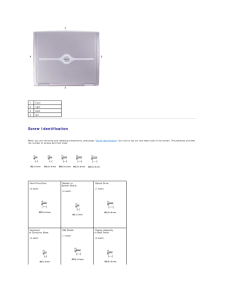
3 .Back to Contents Page Bef...Back to Contents Page Before You BeginDell™ Inspiron™ 1150 Service Manual Computer Orientation Screw Identification This chapter provides procedures for removing and installing the components in your computer. Unless otherwise noted, each procedure assum...
-
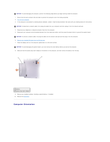
4 .NOTICE: To avoid damaging...NOTICE: To avoid damaging the computer, perform the following steps before you begin working inside the computer.1. Ensure that the work surface is flat and clean to prevent the computer cover from being scratched.2. Turn off your computer.3. If the comput...
-
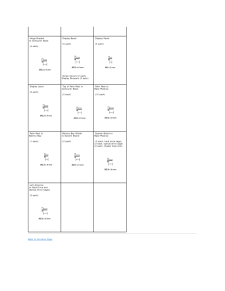
5 .1 front 2 right 3 back ...1 front 2 right 3 back 4 left Screw Identification When you are removing and replacing components, photocopy "Screw Identification" as a tool to lay out and keep track of the screws. The placemat providesthe number of screws and their sizes. Hard Drive...
-
6 .Hinge Bracketto Compu...Hinge Bracketto Computer Base: Display Bezel: Display Panel: (5 each) (4 each) Screw Covers (2 each)Display Bumpers (3 each) (4 each) Display Latch: Top of Palm Rest toComputer Base: Palm Rest toBase Plastics: (2 each) (12 each) Palm Rest toB...
-
7 .Back to Contents Page Fla...Back to Contents Page Flashing the BIOSDell™ Inspiron™ 1150 Service Manual Flashing the BIOS From a Floppy Disk or a CD Flashing the BIOS From the Hard Drive If a BIOS update program floppy disk or CD is provided with the new system board, see "Flashing ...
-
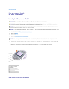
9 .Back to Contents Page Mic...Back to Contents Page Microprocessor ModuleDell™ Inspiron™ 1150 Service Manual Removing the Microprocessor Module CAUTION: Before performing the following procedures, read the safety instructions in your Owner's Manual. CAUTION: To prevent static damage to...
-
10 .NOTICE: Ensure that the c...NOTICE: Ensure that the cam lock is in the fully open position before seating the microprocessor module. Seating the microprocessor module properly inthe ZIF socket does not require force. NOTICE: A microprocessor module that is not properly seated can res...
-
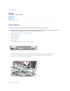
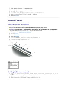
11 .Back to Contents Page Dis...Back to Contents Page DisplayDell™ Inspiron™ 1150 Service Manual Display Assembly Display Bezel Display Panel Display Latch Assembly Display Assembly CAUTION: Before performing the following procedures, read the safety instructions in your Owner's Manu...
-
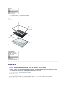
12 .1 pull-tab2 display assem...1 pull-tab2 display assembly3 M2.5 x 5-mm screws (4)4 hinge brackets (2)5 computer base11. Lift the display assembly up and out of the computer base. Display 1 screw covers (2)display bumpers (3)2 M2.5 x 5-mm screws (5)3 display bezel4 display panel5 M2 x...
-
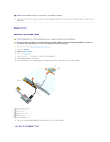
13 .NOTICE: Carefully separa...NOTICE: Carefully separate the bezel from the top cover to avoid damage to the bezel.6. Starting at the bottom of the display panel, use your fingers to separate the bezel from the top cover and lift the inside edge of the bezel away fromthe top cover. Di...
-
14 .1. Connect the top flex-c...1. Connect the top flex-cable connector to the display panel connector.2. Connect the bottom flex-cable connector to the inverter connector.3. Lay the display panel in the top cover.4. Route the display-feed flex cable so that it rests in the notch located...
-
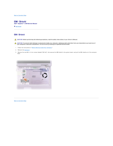
16 .Back to Contents Page EMI...Back to Contents Page EMI ShieldDell™ Inspiron™ 1150 Service Manual EMI Shield EMI Shield CAUTION: Before performing the following procedures, read the safety instructions in your Owner's Manual. CAUTION: To prevent static damage to components inside your...
-
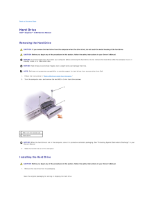
17 .Back to Contents Page Har...Back to Contents Page Hard DriveDell™ Inspiron™ 1150 Service Manual Removing the Hard Drive CAUTION: If you remove the hard drive from the computer when the drive is hot, do not touch the metal housing of the hard drive. CAUTION: Before you begin any of th...
-
18 .NOTICE: Use firm and even...NOTICE: Use firm and even pressure to slide the drive into place. If you use excessive force, you may damage the connector.2. Insert the drive into the bay, and push the hard drive until it is fully seated in the bay.3. Replace and tighten the two M2.5 x 5...
-
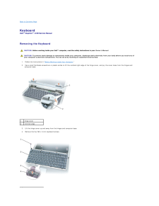
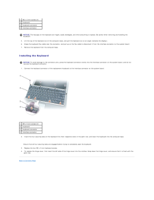
19 .Back to Contents Page Key...Back to Contents Page KeyboardDell™ Inspiron™ 1150 Service Manual Removing the Keyboard CAUTION: Before working inside your Dell™ computer, read the safety instructions in your Owner's Manual. CAUTION: To prevent static damage to components inside your com...
-
20 .1 M2 x 3-mm screws (4)2 k...1 M2 x 3-mm screws (4)2 keyboard3 keyboard connector4 interface connector NOTICE: The keycaps on the keyboard are fragile, easily dislodged, and time-consuming to replace. Be careful when removing and handling thekeyboard.5. Lift the top of the keyboard ou...
-
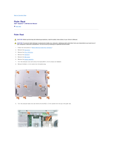
21 .Back to Contents Page Pal...Back to Contents Page Palm RestDell™ Inspiron™ 1150 Service Manual Palm Rest Palm Rest CAUTION: Before performing the following procedures, read the safety instructions in your Owner's Manual. CAUTION: To prevent static damage to components inside your co...
-
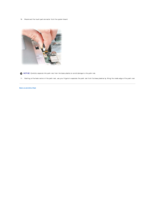
22 .10. Disconnect the touch ...10. Disconnect the touch pad connector from the system board. NOTICE: Carefully separate the palm rest from the base plastics to avoid damage to the palm rest.11. Starting at the back center of the palm rest, use your fingers to separate the palm rest fro...
-
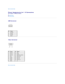
23 .Back to Contents Page Pin...Back to Contents Page Pinout Assignments for I/O ConnectorsDell™ Inspiron™ 1150 Service Manual USB Connector Video Connector USB Connector PinSignal1 USB5V+2 USBP–3 USBP+4 GND Video Connector PinSignalPinSignal1 CRT_R9 5V+2 CRT_G10 GND3 CRT_B11 MONITOR...
-
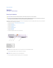
24 .Back to Contents Page Spe...Back to Contents Page SpeakersDell™ Inspiron™ 1150 Service Manual Removing the Speakers CAUTION: Before performing the following procedures, read the safety instructions in your Owner's Manual. CAUTION: To prevent static damage to components inside your co...
-
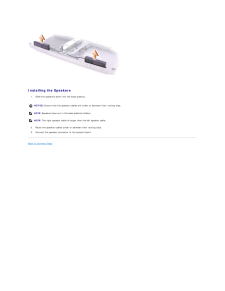
25 .Installing the Speakers1...Installing the Speakers1. Slide the speakers down into the base plastics. NOTICE: Ensure that the speaker cables are under or between their routing clips. NOTE: Speakers face out in the base plastics holders. NOTE: The right speaker cable is longer than t...
-
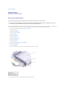
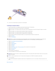
26 .Back to Contents Page Sys...Back to Contents Page System BoardDell™ Inspiron™ 1150 Service Manual Removing the System Board CAUTION: Before performing the following procedures, read the safety instructions in your Owner's Manual. CAUTION: To prevent static damage to components inside...
-
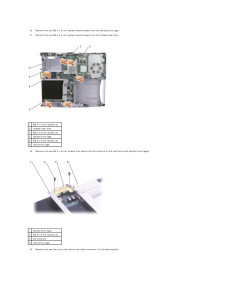
27 .16. Remove the two M2.5 x...16. Remove the two M2.5 x 5-mm system board screws from the optical drive cage.17. Remove the two M2.5 x 5-mm system board screws from the chipset heat sink. 1 M2.5 x 5-mm screws (2)2 chipset heat sink3 M2.5 x 5-mm screws (2)4 optical drive cage5 M2.5 x 5...
-
28 .20. Lift the front of the...20. Lift the front of the system board out and away from the base plastics. Installing the System Board1. Insert the video connector on the replacement system board through the back of the base plastics.2. Replace the two hex nuts that secure the video con...
-
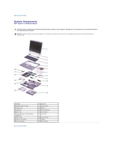
29 .Back to Contents Page Sys...Back to Contents Page System ComponentsDell™ Inspiron™ 1150 Service Manual CAUTION: Only a certified service technician should perform repairs on your computer. Damage due to servicing that is not authorized by Dell isnot covered by your warranty. NOTICE: ...
-
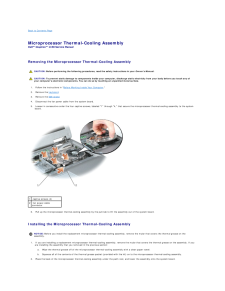
30 .Back to Contents Page Mic...Back to Contents Page Microprocessor Thermal-Cooling AssemblyDell™ Inspiron™ 1150 Service Manual Removing the Microprocessor Thermal-Cooling Assembly CAUTION: Before performing the following procedures, read the safety instructions in your Owner's Manual. ...
-
31 .3. Connect the fan power ...3. Connect the fan power cable to the system board.4. Tighten the four captive screws, labeled "1" through "4," in consecutive order.5. Replace the EMI shield.6. Replace the keyboard.Back to Contents Page
-
32 .Back to Contents PageDell...Back to Contents PageDell™ Inspiron™ 1150 Service ManualNOTE: A NOTE indicates important information that helps you make better use of your computer.NOTICE: A NOTICE indicates either potential damage to hardware or loss of data and tells you how to avoid t...
-
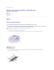
33 .Back to Contents Page Mem...Back to Contents Page Memory, CD or DVD Drive, Modem, and Mini PCI CardDell™ Inspiron™ 1150 Service Manual Memory CD or DVD Drive Modem Mini PCI Card Memory Removing the Memory Modules CAUTION: Before working inside your Dell™ computer, read the safety...
-
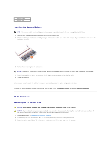
34 .1 memory module2 securin...1 memory module2 securing clips Installing the Memory Modules NOTE: If the memory module is not installed properly, the computer may not boot properly. No error message indicates this failure.1. Align the notch in the module edge connector with the tab in...
-
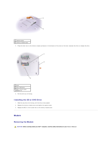
35 .1 captive screw2 memory ...1 captive screw2 memory module cover4. Press the lever next to the memory module connectors in the direction of the arrow on the lever (towards the drive) to release the drive. 1 lever2 CD or DVD drive3 M2.5 x 8-mm screwlabeled "O"5. Pull the drive ou...
-
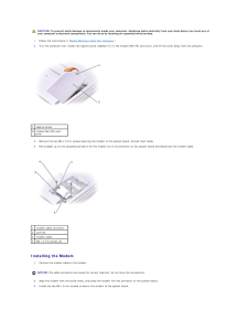
36 .CAUTION: To prevent stati...CAUTION: To prevent static damage to components inside your computer, discharge static electricity from your body before you touch any ofyour computer's electronic components. You can do so by touching an unpainted metal surface.1. Follow the instructions ...
-
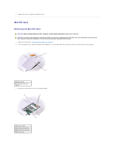
37 .4. Replace the cover and ...4. Replace the cover and tighten the captive screw. Mini PCI Card Removing the Mini PCI Card CAUTION: Before working inside your Dell™ computer, read the safety instructions in your Owner's Manual. CAUTION: To prevent static damage to components inside you...
-
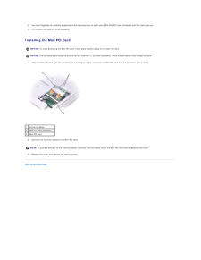
38 .4. Use your fingertips to...4. Use your fingertips to carefully spread apart the securing taps on each end of the Mini PCI card connector until the card pops up. 5. Lift the Mini PCI card out of its connector. Installing the Mini PCI Card NOTICE: To avoid damaging the Mini PCI card, ...
