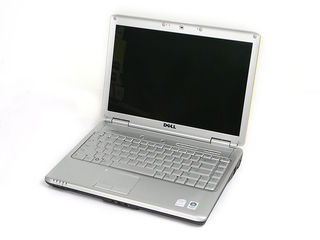
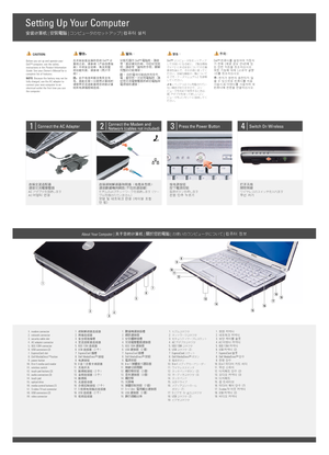
Inspiron 142...
x
Gizport

Inspiron 1420の取扱説明書・マニュアル [全44ページ 1.30MB]

2
inspiron-1420_Service%20Manual_en-us.pdf
gizport - 2013-10-19
ftp://ftp.dell.com/.../inspiron-1420_Service%20Manual_en-us.pdf - 1.30MB - キャッシュ
11173view
44page / 1.30MB
Share (facebook)
2 / 44 ページ
 
2 / 44 ページ
ファイルを開く
現在のページURL
Back to Contents Page  Before You BeginDell™ Inspiron™ 1420/Dell Vostro™ 1400 Service Manual   Recommended Tools  Turning Off Your Computer  Before Working Inside Your ComputerThis section provides procedures for removing and installing the components in your computer. Unless otherwise noted, each procedure assumes that thefollowing conditions exist:l You have performed the steps in Turning Off Your Computer and Before Working Inside Your Computer.l You have read the safety information in the Dell™ Product Information Guide.l A component can be replaced or—if purchased separately—installed by performing the removal procedure in reverse order. Recommended ToolsThe procedures in this document may require the following tools:l Small flat-blade screwdriverl Small Phillips screwdriverl Small plastic scribel Flash BIOS update program CD Turning Off Your ComputerNOTICE: To avoid losing data, save and close all open files and exit all open programs before you turn off your computer.1. Shut down the operating system:a. Save and close all open files and exit all open programs.b. Click the Windows Vista Start button, click the arrow in the lower-right corner of the Start menu as shown below, and then click Shut Down.The computer turns off after the operating system shutdown process is complete.2. Ensure that the computer and all attached devices are turned off. If your computer and attached devices did not automatically turn off when you shutdown your operating system, press and hold the power button for about 4 seconds to turn them off. Before Working Inside Your ComputerUse the following safety guidelines to help protect your computer from potential damage and to help to ensure your own personal safety. CAUTION: Before you begin any of the procedures in this section, follow the safety instructions in the Product Information Guide.NOTICE: Handle components and cards with care. Do not touch the components or contacts on a card. Hold a card by its edges or by its metalmounting bracket. Hold a component such as a processor by its edges, not by its pins.NOTICE: Only a certified service technician should perform repairs on your computer. Damage due to servicing that is not authorized by Dell is notcovered by your warranty.NOTICE: When you disconnect a cable, pull on its connector or on its pull-tab, not on the cable itself. Some cables have connectors with locking tabs; ifyou are disconnecting this type of cable, press in on the locking tabs before you disconnect the cable. As you pull connectors apart, keep them evenlyaligned to avoid bending any connector pins. Also, before you connect a cable, ensure that both connectors are correctly oriented and aligned.NOTICE: To avoid damaging the computer, perform the following steps before you begin working inside the computer.1. Ensure that the work surface is flat and clean to prevent the computer cover from being scratched. 

参考になったと評価
  4人が参考になったと評価しています。

その他の取扱説明書
749 view
363 view

このマニュアルの目次

  • 1 .
    Dell™ Inspiron™ 1420/Dell...
    Dell™ Inspiron™ 1420/Dell Vostro™ 1400 Service Manual Before You BeginDisplayInternal Card With Bluetooth® Wireless TechnologyCamera ModuleOptical DrivePalm RestHard DriveFanMemoryMicroprocessor Thermal-Cooling AssemblyModemMicroprocessor ModuleCoin-Cell B...
  • 2 .
    Back to Contents Page  Be...
    Back to Contents Page  Before You BeginDell™ Inspiron™ 1420/Dell Vostro™ 1400 Service Manual   Recommended Tools  Turning Off Your Computer  Before Working Inside Your ComputerThis section provides procedures for removing and installing the components in y...
  • 3 .
    2.Turn off your computer ...
    2.Turn off your computer (see Turning Off Your Computer).NOTICE: To disconnect a network cable, first unplug the cable from your computer and then unplug the cable from the network device.3. Disconnect all telephone or network cables from the computer.NOTI...
  • 4 .
    Back to Contents Page  Fl...
    Back to Contents Page  Flashing the BIOSDell™ Inspiron™ 1420/Dell Vostro™ 1400 Service Manual 1. Download the BIOS utility from the Dell Support website at support.dell.com and save it to your desktop.2. After the download completes, double-click the BIOS ...
  • 5 .
    Back to Contents Page  In...
    Back to Contents Page  Internal Card With Bluetooth® Wireless TechnologyDell™ Inspiron™ 1420/Dell Vostro™ 1400 Service Manual   Removing and Replacing Internal Card With Bluetooth® Wireless Technology CAUTION: Before you begin any of the procedures in this...
  • 6 .
    Back to Contents Page  Ca...
    Back to Contents Page  Camera ModuleDell™ Inspiron™ 1420/Dell Vostro™ 1400 Service Manual   Removing and Replacing the Camera Module Removing and Replacing the Camera Module CAUTION: Before you perform any of the procedures in this section, follow the safe...
  • 7 .
    Back to Contents Page  Co...
    Back to Contents Page  Coin-Cell BatteryDell™ Inspiron™ 1420/Dell Vostro™ 1400 Service Manual   Removing the Coin-Cell Battery  Replacing the Coin-Cell Battery CAUTION: Before you begin any of the procedures in this section, follow the safety instructions ...
  • 8 .
    Back to Contents Page  Mi...
    Back to Contents Page  Microprocessor ModuleDell™ Inspiron™ 1420/Dell Vostro™ 1400 Service Manual   Removing the Microprocessor Module  Replacing the Microprocessor Module Removing the Microprocessor Module CAUTION: Before you perform any of the procedures...
  • 9 .
    1microprocessor module2ZI...
    1microprocessor module2ZIF-socket3ZIF-socket cam screwNOTICE: When removing the microprocessor module, pull the module straight up and out of the ZIF-socket. Exercise care not to bend the pins on themicroprocessor module.NOTE: The microprocessor module and...
  • 10 .
    Back to Contents Page 
    Back to Contents Page 
  • 11 .
    Back to Contents Page  Mi...
    Back to Contents Page  Microprocessor Thermal-Cooling AssemblyDell™ Inspiron™ 1420/Dell Vostro™ 1400 Service Manual   Removing the Microprocessor Thermal-Cooling Assembly  Replacing the Microprocessor Thermal-Cooling Assembly Removing the Microprocessor Th...
  • 12 .
    1. Follow the instruction...
    1. Follow the instructions in Before You Begin.2. Follow the instructions in Replacing the Microprocessor Module.3. Align the four captive screws on the new microprocessor thermal-cooling assembly with the screw holes on the system board.4. Tighten the fou...
  • 13 .
    Back to Contents Page  Di...
    Back to Contents Page  DisplayDell™ Inspiron™ 1420/Dell Vostro™  1400Service Manual   Removing the Display Assembly  Replacing the Display Assembly  Removing the Display Bezel  Replacing the Display Bezel  Removing the Display Panel  Replacing the Display ...
  • 14 .
    1media buttons board1scre...
    1media buttons board1screws (2)1screws (2)11.12.222main battery bayscrew3back of the system3grips (5)bottom of the system3hinge covers (2) Remove the four M2.5 x 5-mm screws (one on each side of the main battery bay and one below each hinge cover) that con...
  • 15 .
    6.Connect the Mini-Card a...
    6.Connect the Mini-Card antenna cable connectors.7. Replace the media buttons board by sliding it in place.8. Tighten the screw to secure the media buttons board.9. Connect the display cable to the system board.10. Replace the left and right hinge covers b...
  • 16 .
    CAUTION: Before you perfo...
    CAUTION: Before you perform any of the procedures in this section, follow the safety instructions in the Product Information Guide.NOTICE: To avoid electrostatic discharge, ground yourself by using a wrist grounding strap or by periodically touching an unp...
  • 17 .
    1display panel2display co...
    1display panel2display cover3camera module connector4camera5camera module  5. Lift the cable securing tab and gently pull to disconnect the camera module cable from the connector.6. Gently lift the bottom of the display panel up, then slide the display pan...
  • 18 .
    3. Replace the six M2 x 3...
    3. Replace the six M2 x 3-mm screws (three on each side) to secure the display bracket to the display panel.4. Connect the camera module cable from the connector.5. Connect the top flex-cable connector to the display locking connector on the new display pa...
  • 19 .
    Back to Contents Page  Fa...
    Back to Contents Page  FanDell™ Inspiron™ 1420/Dell Vostro™ 1400 Service Manual   Removing the Fan  Replacing the Fan Removing the Fan CAUTION: Before you perform any of the procedures in this section, follow the safety instructions in the Product Informat...
  • 20 .
    Back to Contents Page 
    Back to Contents Page 
  • 21 .
    Back to Contents Page  In...
    Back to Contents Page  Intel® Turbo MemoryDell™ Inspiron™ 1420/Dell Vostro™ 1400 Service Manual   Removing the FCM  Replacing the FCMThe Intel Turbo Memory also called Flash Cache Module (FCM), is an internal flash drive that helps improve the performance ...
  • 22 .
    4. Replace the keyboard c...
    4. Replace the keyboard cover (see Replacing the Keyboard Cover).Back to Contents Page 
  • 23 .
    Back to Contents Page  Ha...
    Back to Contents Page  Hard DriveDell™ Inspiron™ 1420/Dell Vostro™ 1400 Service Manual   Removing the Hard Drive  Replacing the Hard Drive CAUTION: If you remove the hard drive from the computer when the drive is hot, do not touch the metal housing of the ...
  • 24 .
    1screws (2)6.2hard drive ...
    1screws (2)6.2hard drive assembly3hard drive Slide out the hard drive from the hard drive assembly.NOTICE: When the hard drive is not in the computer, store it in protective antistatic packaging (see "Protecting Against Electrostatic Discharge" in theProdu...
  • 25 .
    Back to Contents Page  Ke...
    Back to Contents Page  Keyboard CoverDell™ Inspiron™ 1420/Dell Vostro™ 1400 Service Manual   Removing the Keyboard Cover  Replacing the Keyboard Cover CAUTION: Before you begin any of the procedures in this section, follow the safety instructions in the Pr...
  • 26 .
    Back to Contents Page  Ke...
    Back to Contents Page  KeyboardDell™ Inspiron™ 1420/Dell Vostro™ 1400 Service Manual   Removing the Keyboard  Replacing the Keyboard CAUTION: Before you begin any of the procedures in this section, follow the safety instructions in the Product Information ...
  • 27 .
    3. Hook the tabs along th...
    3. Hook the tabs along the front edge of the keyboard into the palmrest.4. Press on the right edge near the top to snap the keyboard into place.5. Replace the two screws to secure the keyboard.Back to Contents Page 
  • 28 .
    Back to Contents Page  Me...
    Back to Contents Page  MemoryDell™ Inspiron™ 1420/Dell Vostro™ 1400 Service Manual   Removing the Memory Module  Replacing the Memory ModuleYou can increase your computer memory by installing memory modules on the system board. Install only memory modules ...
  • 29 .
    1memory module2securing c...
    1memory module2securing clips(2) Replacing the Memory ModuleNOTICE: To avoid electrostatic discharge, ground yourself by using a wrist grounding strap or by periodically touching an unpainted metal surface (suchas a connector on the back of the computer).1...
  • 30 .
    Back to Contents Page  Co...
    Back to Contents Page  Communication CardsDell™ Inspiron™ 1420/Dell Vostro™ 1400 Service Manual   Removing a WLAN Card  Replacing a WLAN Card  Removing a Mobile Broadband or WWAN Card  Replacing a WWAN CardIf you ordered a wireless Mini-Card with your comp...
  • 31 .
     Replacing a WLAN CardNOT...
     Replacing a WLAN CardNOTICE: The connectors are keyed to ensure correct insertion. If you feel resistance, check the connectors on the card and on the system board, andrealign the card.NOTICE: To avoid damage to the WLAN card, never place cables under the...
  • 32 .
    1WWAN card6.2antenna cabl...
    1WWAN card6.2antenna cables (2) Pull the WWAN card out of its system board connector. Replacing a WWAN CardNOTICE: The connectors are keyed to ensure correct insertion. If you feel resistance, check the connectors on the card and on the system board, andre...
  • 33 .
    Back to Contents Page  Mo...
    Back to Contents Page  ModemDell™ Inspiron™ 1420/Dell Vostro™ 1400 Service Manual   Removing and Replacing the Modem Removing and Replacing the Modem CAUTION: Before you begin any of the procedures in this section, follow the safety instructions located in...
  • 34 .
    Back to Contents Page  Op...
    Back to Contents Page  Optical DriveDell™ Inspiron™ 1420/Dell Vostro™ 1400 Service Manual   Removing the Optical Drive  Replacing the Optical Drive CAUTION: Before you begin any of the procedures in this section, follow the safety instructions in the Produ...
  • 35 .
    Back to Contents Page  Pa...
    Back to Contents Page  Palm RestDell™ Inspiron™ 1420/Dell Vostro™ 1400 Service Manual   Removing the Palm Rest  Replacing the Palm Rest Removing the Palm Rest CAUTION: Before you perform any of the procedures in this section, follow the safety instructions...
  • 36 .
    1palm rest8.2M2.5 x 5mm s...
    1palm rest8.2M2.5 x 5mm screws (3)3Bottom of the system Disconnect the touch pad cable.Use a plastic scribe to release the locking clips on both sides of the system board connector, and then gently pull to disconnect the touch pad connectorfrom the system ...
  • 37 .
    3.Align the new palm rest...
    3.Align the new palm rest with the base of the computer, and then snap the palm rest into place.NOTICE: To prevent damage to the cables or the cable connectors, ensure that the locking clips on both sides of each system board connector arefirmly seated and...
  • 38 .
    Back to Contents Page  Pi...
    Back to Contents Page  Pin Assignments for I/O ConnectorsDell™ Inspiron™ 1420/Dell Vostro™ 1400 Service Manual   USB Connector  Video Connector  S-Video TV-Out Connector  IEEE 1394 Connector USB Connector  Pin Signal1USB5V+2USBP–3USBP+4GND Video Connector ...
  • 39 .
    1GND2GND3DLUMA-L4DCRMA-L ...
    1GND2GND3DLUMA-L4DCRMA-L Composite Video  PinSignal5GND6DCMPS-L7NC IEEE 1394 Connector  Pin Signal1TPB–2TPB+3TPA–4TPA+Back to Contents Page 
  • 40 .
    Back to Contents Page  Sp...
    Back to Contents Page  SpeakersDell™ Inspiron™ 1420/Dell Vostro™ 1400 Service Manual   Removing the Speakers  Replacing the Speakers Removing the Speakers CAUTION: Before you perform any of the procedures in this section, follow the safety instructions in ...
  • 41 .
    3. Place each of the new ...
    3. Place each of the new speakers in the appropriate speaker slot.NOTE: For proper placement, align the slots on the speakers with the screw-hole guide posts on the base of the computer.4. Replace the two M2.5 x 5-mm screws to secure the speakers to the ba...
  • 42 .
    Back to Contents Page  Sy...
    Back to Contents Page  System BoardDell™ Inspiron™ 1420/Dell Vostro™ 1400 Service Manual   Removing the System Board  Replacing the System Board Removing the System Board CAUTION: Before you perform any of the procedures in this section, follow the safety ...
  • 43 .
    1IO panel connector2speak...
    1IO panel connector2speaker connector18.system board Take out the system board and keep it aside.19.3 Disconnect the modem cable from the system board.20. With the rear of the computer facing you, gently lift the system board assembly from the left side, t...
  • 44 .
    Back to Contents PageDell...
    Back to Contents PageDell™ Inspiron™ 1420/Dell Vostro™ 1400 Service Manual  Notes, Notices, and CautionsNOTE: A NOTE indicates important information that helps you make better use of your computer.NOTICE: A NOTICE indicates either potential damage to hardw...