
Inspiron 1525の取扱説明書・マニュアル [全51ページ 1.51MB]


1


1 / 51 ページ
1 / 51 ページ


現在のページURL
Dell™ Inspiron™ 1525/1526 Service Manual Before You BeginSubscriber Identity Module (Optional)ExpressCardsUsing the Memory Card ReaderOptical DriveHard DriveCenter Control CoverInternal Card With Bluetooth® Wireless TechnologyKeyboardButton BoardMemoryDisplaySpeaker AssemblyPalm RestExpressCard CageProcessor Thermal-Cooling AssemblyProcessor ModuleWireless Mini-CardsSystem Board AssemblyCoin-Cell BatteryBattery Latch AssemblyFlashing the BIOSPin Assignments for I/O Connectors Notes, Notices, and CautionsNOTE: A NOTE indicates important information that helps you make better use of your computer.NOTICE: A NOTICE indicates either potential damage to hardware or loss of data and tells you how to avoid the problem.CAUTION: A CAUTION indicates potential for property damage, personal injury, or death.Information in this document is subject to change without notice.© 2007–2008 Dell Inc. All rights reserved.Reproduction in any manner whatsoever without the written permission of Dell Inc. is strictly forbidden.Trademarks used in this text: Dell, the DELL logo, and Inspiron are trademarks of Dell Inc.; Microsoft, Windows, and Windows Vista are either trademarks or registered trademarks ofMicrosoft Corporation in the United States and/or other countries.Other trademarks and trade names may be used in this document to refer to either the entities claiming the marks and names or their products. Dell Inc. disclaims anyproprietary interest in trademarks and trade names other than its own.Model PP29LJanuary 2008 Rev. A00
参考になったと評価  19人が参考になったと評価しています。
その他の取扱説明書

2460 view
このマニュアルの目次
-
1 .Dell™ Inspiron™ 1525/1526...Dell™ Inspiron™ 1525/1526 Service Manual Before You BeginSubscriber Identity Module (Optional)ExpressCardsUsing the Memory Card ReaderOptical DriveHard DriveCenter Control CoverInternal Card With Bluetooth® Wireless TechnologyKeyboardButton BoardMemoryDisp...
-
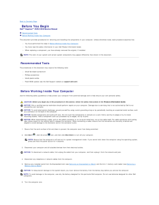
2 .Back to Contents Page Be...Back to Contents Page Before You BeginDell™ Inspiron™ 1525/1526 Service Manual Recommended Tools Before Working Inside Your ComputerThis document provides procedures for removing and installing the components in your computer. Unless otherwise noted, e...
-
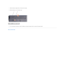
3 .7.Slide the battery relea...7.Slide the battery release latch until they click into place.8. Slide the battery out of the battery bay.1 battery 2 battery release latch9. Turn the computer top-side up, open the display, and press the power button to ground the system board.Back to Con...
-
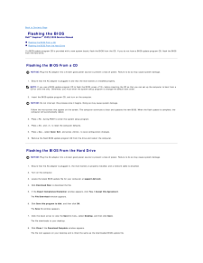
4 .Back to Contents Page Fl...Back to Contents Page Flashing the BIOSDell™ Inspiron™ 1525/1526 Service Manual Flashing the BIOS From a CD Flashing the BIOS From the Hard DriveIf a BIOS-update program CD is provided with a new system board, flash the BIOS from the CD. If you do not ...
-
5 .9.Double-click the file i...9.Double-click the file icon on the desktop and follow the instructions on the screen.Back to Contents Page
-
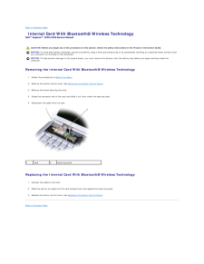
6 .Back to Contents Page In...Back to Contents Page Internal Card With Bluetooth® Wireless TechnologyDell™ Inspiron™ 1525/1526 Service Manual CAUTION: Before you begin any of the procedures in this section, follow the safety instructions in the Product Information Guide.NOTICE: To av...
-
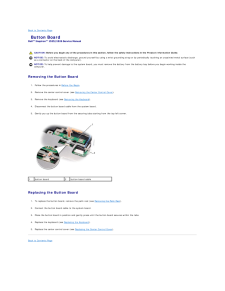
7 .Back to Contents Page Bu...Back to Contents Page Button BoardDell™ Inspiron™ 1525/1526 Service Manual CAUTION: Before you begin any of the procedures in this section, follow the safety instructions in the Product Information Guide.NOTICE: To avoid electrostatic discharge, ground y...
-
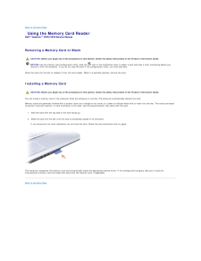
8 .Back to Contents Page Us...Back to Contents Page Using the Memory Card ReaderDell™ Inspiron™ 1525/1526 Service Manual Removing a Memory Card or Blank CAUTION: Before you begin any of the procedures in this section, follow the safety instructions in the Product Information Guide.NO...
-
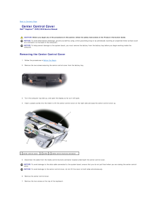
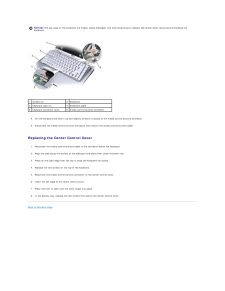
9 .Back to Contents Page Ce...Back to Contents Page Center Control CoverDell™ Inspiron™ 1525/1526 Service Manual CAUTION: Before you begin any of the procedures in this section, follow the safety instructions in the Product Information Guide.NOTICE: To avoid electrostatic discharge, ...
-
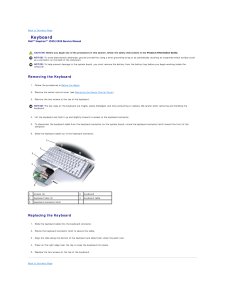
10 .NOTICE: The key caps on t...NOTICE: The key caps on the keyboard are fragile, easily dislodged, and time-consuming to replace. Be careful when removing and handling thekeyboard.1screws (2)2keyboard3keyboard tabs (5)4keyboard cable5keyboard connector latch6media control buttons connec...
-
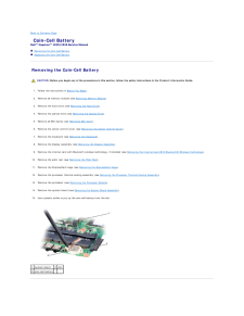
11 .Back to Contents Page Co...Back to Contents Page Coin-Cell BatteryDell™ Inspiron™ 1525/1526 Service Manual Removing the Coin-Cell Battery Replacing the Coin-Cell Battery Removing the Coin-Cell Battery CAUTION: Before you begin any of the procedures in this section, follow the sa...
-
12 .Replacing the Coin-Cell ...Replacing the Coin-Cell Battery CAUTION: Before you begin the following procedure, follow the safety instructions in the Product Information Guide.1. Hold the coin-cell battery with the positive side up.2. Slide the coin-cell battery into the slot and gen...
-
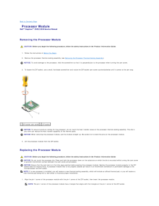
13 .Back to Contents Page Pr...Back to Contents Page Processor ModuleDell™ Inspiron™ 1525/1526 Service Manual Removing the Processor Module CAUTION: Before you begin the following procedure, follow the safety instructions in the Product Information Guide.1. Follow the instructions in ...
-
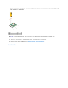
14 .When the processor module...When the processor module is properly seated, all four corners are aligned at the same height. If one or more corners of the module are higher than theothers, the module is not seated properly.1 ZIF-socket cam screw 2 ZIF socket3 pin-1 corner NOTICE: To a...
-
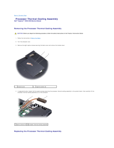
15 .Back to Contents Page Pr...Back to Contents Page Processor Thermal-Cooling AssemblyDell™ Inspiron™ 1525/1526 Service Manual Removing the Processor Thermal-Cooling Assembly CAUTION: Before you begin the following procedure, follow the safety instructions in the Product Information ...
-
16 .CAUTION: Before you begi...CAUTION: Before you begin the following procedure, follow the safety instructions in the Product Information Guide.1. Align the five captive screws on the processor thermal-cooling assembly with the screw holes on the system board.2. In sequential order, ...
-
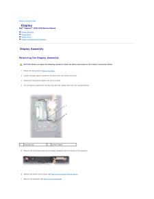
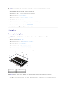
17 .Back to Contents Page Di...Back to Contents Page DisplayDell™ Inspiron™ 1525/1526 Service Manual Display Assembly Display Bezel Display Panel Camera and Microphone Assembly Display Assembly Removing the Display Assembly CAUTION: Before you begin the following procedure, follow...
-
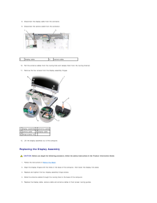
18 .8. Disconnect the display...8. Disconnect the display cable from the connector.9. Disconnect the camera cable from the connector.1display cable2camera cable10. Pull the antenna cables from the routing hole and release them from the routing channel.11. Remove the four screws from the ...
-
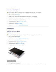
19 .NOTE: Ensure that the dis...NOTE: Ensure that the display cable, camera cable, and antenna cables are properly routed and secured beneath the plastic tabs.6. Connect the display cable to the display cable connector on the system board.7. Connect the camera cables to the camera cable ...
-
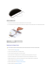
20 .remainder of the bezel. R...remainder of the bezel. Replacing the Display Bezel CAUTION: Before you begin the following procedure, follow the safety instructions in the Product Information Guide.1. Follow the instructions in Before You Begin.2. Starting at any corner, use your finger...
-
21 .1 display panel 2 screws ...1 display panel 2 screws (8)9.10. Use the pull tab to disconnect the bottom flex-cable connector from the invertor connector. Lift the tape securing the top flex-cable connector and gently pull to disconnect the top flex-cable connector from the display lo...
-
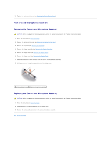
22 .10. Replace the center co...10. Replace the center control cover (see Replacing the Center Control Cover). Camera and Microphone Assembly Removing the Camera and Microphone Assembly CAUTION: Before you begin the following procedure, follow the safety instructions in the Product Infor...
-
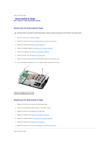
23 .Back to Contents Page Ex...Back to Contents Page ExpressCard CageDell™ Inspiron™ 1525/1526 Service Manual Removing the ExpressCard Cage CAUTION: Before you begin the following procedure, follow the safety instructions in the Product Information Guide.1. Follow the instructions in ...
-
24 .24 ページ目のマニュアル
-
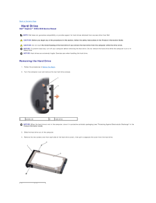
25 .Back to Contents Page Ha...Back to Contents Page Hard DriveDell™ Inspiron™ 1525/1526 Service Manual NOTE: Dell does not guarantee compatibility or provide support for hard drives obtained from sources other than Dell. CAUTION: Before you begin any of the procedures in this section,...
-
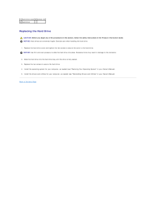
26 .1 hard drive cover 2 scre...1 hard drive cover 2 screws (2)3 hard drive Replacing the Hard Drive CAUTION: Before you begin any of the procedures in this section, follow the safety instructions in the Product Information Guide.NOTICE: Hard drives are extremely fragile. Exercise care...
-
27 .Back to Contents Page Ke...Back to Contents Page KeyboardDell™ Inspiron™ 1525/1526 Service Manual CAUTION: Before you begin any of the procedures in this section, follow the safety instructions in the Product Information Guide.NOTICE: To avoid electrostatic discharge, ground yours...
-
28 .28 ページ目のマニュアル
-
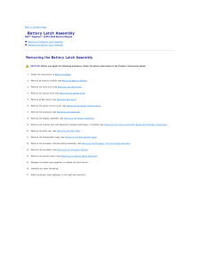
29 .Back to Contents Page Ba...Back to Contents Page Battery Latch AssemblyDell™ Inspiron™ 1525/1526 Service Manual Removing the Battery Latch Assembly Replacing the Battery Latch Assembly Removing the Battery Latch Assembly CAUTION: Before you begin the following procedure, follow ...
-
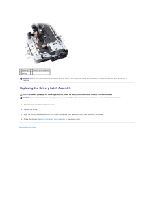
30 .1 plastic grip 2 battery ...1 plastic grip 2 battery latch assembly3 spring NOTICE: Before you remove the battery release button, observe the orientation of the button to ensure proper installation when the button isreplaced. Replacing the Battery Latch Assembly CAUTION: Before you ...
-
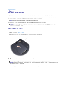
31 .Back to Contents Page Me...Back to Contents Page MemoryDell™ Inspiron™ 1525/1526 Service Manual CAUTION: Before you begin any of the procedures in this section, follow the safety instructions in the Product Information Guide.You can increase your computer memory by installing memo...
-
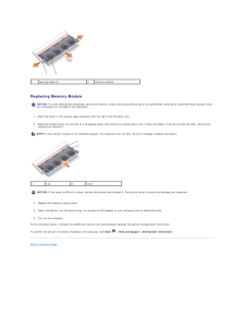
32 .1securing clips (2)2memor...1securing clips (2)2memory module Replacing Memory ModuleNOTICE: To avoid electrostatic discharge, ground yourself by using a wrist grounding strap or by periodically touching an unpainted metal surface (suchas a connector on the back of the computer).1.2....
-
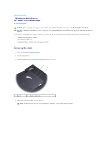
33 .Back to Contents Page Wi...Back to Contents Page Wireless Mini-CardsDell™ Inspiron™ 1525/1526 Service Manual Flash Cache Module CAUTION: Before you begin any of the procedures in this section, follow the safety instructions in the Product Information Guide.NOTICE: To help prevent...
-
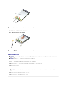
34 .1antenna cable connectors...1antenna cable connectors2securing screw5. Release the Mini-card by removing the securing screw.6. Lift the card out of its system board connector.1Mini-card Replacing Mini-CardNOTICE: The connectors are keyed to ensure correct insertion. If you feel resis...
-
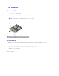
35 .Flash Cache Module Remov...Flash Cache Module Removing the FCM1. Follow the procedures in Before You Begin.2. Turn the computer over and remove the cover on the Mini Card compartment.3. Ground yourself by touching one of the metal connectors on the back of the computer.NOTE: If you...
-
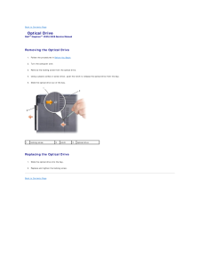
36 .Back to Contents Page Op...Back to Contents Page Optical DriveDell™ Inspiron™ 1525/1526 Service Manual Removing the Optical Drive1. Follow the procedures in Before You Begin.2. Turn the computer over.3. Remove the locking screw from the optical drive.4. Using a plastic scribe or s...
-
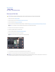
37 .Back to Contents Page Pa...Back to Contents Page Palm RestDell™ Inspiron™ 1525/1526 Service Manual Removing the Palm Rest CAUTION: Before you begin the following procedure, follow the safety instructions in the Product Information Guide.1. Follow the instructions in Before You Beg...
-
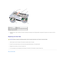
38 .1 screws (2)2 palm rest3 ...1 screws (2)2 palm rest3 touch pad connector 4 device status lights LED connector5 display hinge screw11. Moving from left to right, carefully lift the palm rest along the rear edge, near the hinge brackets, then gently lift the palm rest to remove it fr...
-
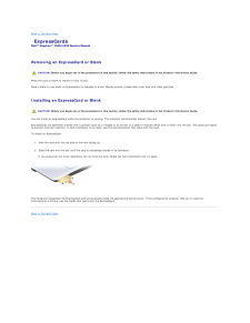
39 .Back to Contents Page Ex...Back to Contents Page ExpressCardsDell™ Inspiron™ 1525/1526 Service Manual Removing an ExpressCard or Blank CAUTION: Before you begin any of the procedures in this section, follow the safety instructions in the Product Information Guide.Press the card or...
-
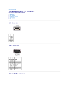
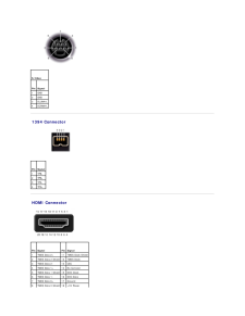
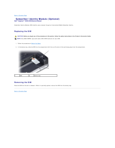
40 .Back to Contents Page Pi...Back to Contents Page Pin Assignments for I/O ConnectorsDell™ Inspiron™ 1525/1526 Service Manual USB Connector Video Connector S-Video TV-Out Connector 1394 Connector HDMI Connector USB Connector Pin Signal1USB5V+2USBP–3USBP+4GND Video Connector ...
-
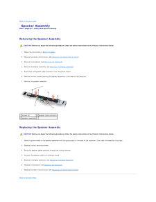
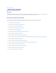
41 .S-Video Pin Signal1GND2...S-Video Pin Signal1GND2GND3DLUMA-L4DCRMA-L 1394 Connector Pin Signal1TPB-2TPB+3TPA-4TPA+ HDMI Connector Pin SignalPin Signal1TMDS Data 2+112TMDS Data 2 Shield 12TMDS Clock-3TMDS Data 2-13CEC4TMDS Data 1+14No Connect5TMDS Data 1 Shield 15DDC Clock6TMD...
-
42 .9TMDS Data 0-19Hot Plug D...9TMDS Data 0-19Hot Plug Detect10TMDS Clock+20SHELLBack to Contents Page
-
43 .Back to Contents Page Su...Back to Contents Page Subscriber Identity Module (Optional)Dell™ Inspiron™ 1525/1526 Service Manual Subscriber Identity Modules (SIM) identify users uniquely through an International Mobile Subscriber Identity. Replacing the SIM CAUTION: Before you begin ...
-
44 .Back to Contents Page Sp...Back to Contents Page Speaker AssemblyDell™ Inspiron™ 1525/1526 Service Manual Removing the Speaker Assembly CAUTION: Before you begin the following procedure, follow the safety instructions in the Product Information Guide.1. Follow the instructions in ...
-
45 .45 ページ目のマニュアル
-
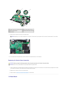
46 .Back to Contents Page Sy...Back to Contents Page System Board AssemblyDell™ Inspiron™ 1525/1526 Service Manual S-Video Board Charger BoardThe system board's BIOS chip contains the Service Tag, which is also visible on a barcode label on the bottom of the computer. The replacemen...
-
47 .1 processor heat sink fan...1 processor heat sink fan cable connector 2 button board cable connector3 speaker cable connector4 wireless sniffer board connector5 system board 17. Remove the four screws from the top of the system board.NOTE: Depending on your system configuration, the...
-
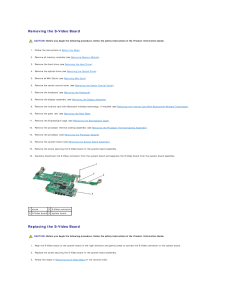
48 .Removing the S-Video Boar...Removing the S-Video Board CAUTION: Before you begin the following procedure, follow the safety instructions in the Product Information Guide.1. Follow the instructions in Before You Begin.2. Remove all memory modules (see Removing Memory Module).3. Remove...
-
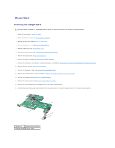
49 .Charger Board Removing t...Charger Board Removing the Charger Board CAUTION: Before you begin the following procedure, follow the safety instructions in the Product Information Guide.1. Follow the instructions in Before You Begin.2. Remove all memory module (see Removing Memory Mod...
-
50 .Replacing the Charger Boa...Replacing the Charger Board CAUTION: Before you begin the following procedure, follow the safety instructions in the Product Information Guide.1. Align the charger board to the system board in the right direction and gently press to connect the charger boa...
-
51 .Back to Contents PageDell...Back to Contents PageDell™ Inspiron™ 1525/1526 Service Manual NOTE: A NOTE indicates important information that helps you make better use of your computer.NOTICE: A NOTICE indicates either potential damage to hardware or loss of data and tells you how to a...
