
Vostro 1510の取扱説明書・マニュアル [全62ページ 1.36MB]


3


1 / 62 ページ
1 / 62 ページ


現在のページURL
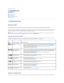
Dell™ Vostro™ 1510 Service ManualTroubleshootingBefore Working on Your ComputerHard DriveWireless Local Area Network (WLAN) CardFanProcessor Thermal-Cooling AssemblyProcessor ModuleMemoryHinge CoverKeyboardPower Button and Multimedia Button PadsDisplayPalm RestFingerprint ReaderInternal Card With Bluetooth® Wireless TechnologyOptical DriveSystem Board AssemblySpeaker AssemblyUSB Daughter CardBattery Latch AssemblyCoin-Cell BatteryFlashing the BIOSModel PP36L Notes, Notices, and CautionsNOTE: A NOTE indicates important information that helps you make better use of your computer.NOTICE: A NOTICE indicates either potential damage to hardware or loss of data and tells you how to avoid the problem.CAUTION: A CAUTION indicates potential for property damage, personal injury, or death.If you purchased a DELL™ n Series computer, any references in this document to Microsoft® Windows® operating systems are not applicable.Information in this document is subject to change without notice.© 2008 Dell Inc. All rights reserved.Reproduction in any manner whatsoever without the written permission of Dell Inc. is strictly forbidden.Trademarks used in this text: Dell, the DELL logo, and Vostro are trademarks of Dell Inc.; Microsoft, Windows, Windows Vista, and the Windows start button logo are either trademarksor registered trademarks of Microsoft Corporation in the United States and/or other countries. Bluetooth is a registered trademark of Bluetooth SIG Inc.Other trademarks and trade names may be used in this document to refer to either the entities claiming the marks and names or their products. Dell Inc. disclaims anyproprietary interest in trademarks and trade names other than its own.September 2009 Rev. A01
参考になったと評価  5人が参考になったと評価しています。
その他の取扱説明書

29404 view

884 view

1604 view

748 view

1132 view
このマニュアルの目次
-
1 .Dell™ Vostro™ 1510 Servic...Dell™ Vostro™ 1510 Service ManualTroubleshootingBefore Working on Your ComputerHard DriveWireless Local Area Network (WLAN) CardFanProcessor Thermal-Cooling AssemblyProcessor ModuleMemoryHinge CoverKeyboardPower Button and Multimedia Button PadsDisplayPalm...
-
2 .Back to Contents Page Be...Back to Contents Page Before Working on Your ComputerDell™ Vostro™ 1510 Service Manual Recommended Tools What You Need to Know for Your SafetyThis document provides procedures for removing and installing the components in your computer. Unless otherwise...
-
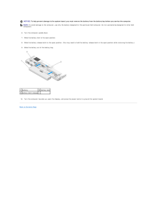
3 .NOTICE: To help prevent ...NOTICE: To help prevent damage to the system board, you must remove the battery from the battery bay before you service the computer.NOTE: To avoid damage to the computer, use only the battery designed for this particular Dell computer. Do not use batteri...
-
4 .Back to Contents Page Fl...Back to Contents Page Flashing the BIOSDell™ Vostro™ 1510 Service Manual Flashing the BIOS From a CD Flashing the BIOS From the Hard DriveIf a BIOS-update program media, such as a CD, is provided with a new system board, flash the BIOS from the media. I...
-
5 .6.In the File Download wi...6.In the File Download window, click Save this program to disk, and then click OK.7. In the Save In window, click the down arrow to view the Save In menu, select Desktop, and then click Save.The file downloads to your desktop.8. Click Close if the Download...
-
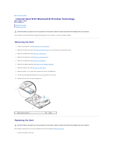
6 .Back to Contents Page In...Back to Contents Page Internal Card With Bluetooth® Wireless TechnologyDell™ Vostro™ 1510 Service Manual Removing the Card Replacing the Card CAUTION: Before you begin any of the procedures in this section, follow the safety instructions that shipped wi...
-
7 .2. Replace the card in th...2. Replace the card in the card compartment.3. Replace the M2 x 3-mm screw that connects the card to the USB board.4. Replace the palm rest (see Replacing the Palm Rest).5. Replace the display assembly (see Replacing the Display Assembly).6. Replace the ke...
-
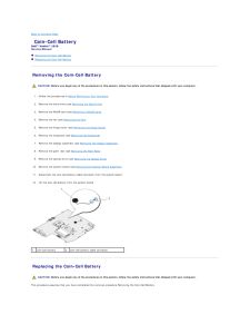
8 .Back to Contents Page Co...Back to Contents Page Coin-Cell BatteryDell™ Vostro™ 1510 Service Manual Removing the Coin-Cell Battery Replacing the Coin-Cell Battery Removing the Coin-Cell Battery CAUTION: Before you begin any of the procedures in this section, follow the safety ins...
-
9 .1.Connect the coin-cell b...1.Connect the coin-cell battery cable to the system board.2. Position the coin-cell battery on the system board.3. Replace the system board (see Replacing the System Board Assembly).4. Replace the optical drive (see Replacing the Optical Drive).5. Replace ...
-
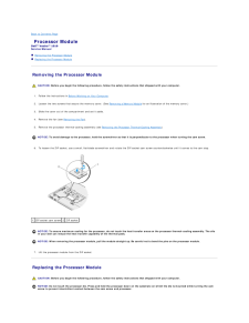
10 .Back to Contents Page Pr...Back to Contents Page Processor ModuleDell™ Vostro™ 1510 Service Manual Removing the Processor Module Replacing the Processor Module Removing the Processor Module CAUTION: Before you begin the following procedure, follow the safety instructions that shi...
-
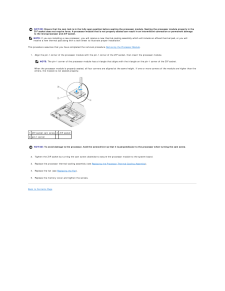
11 .NOTICE: Ensure that the c...NOTICE: Ensure that the cam lock is in the fully open position before seating the processor module. Seating the processor module properly in theZIF socket does not require force. A processor module that is not properly seated can result in an intermittent ...
-
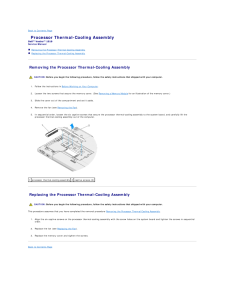
12 .Back to Contents Page Pr...Back to Contents Page Processor Thermal-Cooling AssemblyDell™ Vostro™ 1510 Service Manual Removing the Processor Thermal-Cooling Assembly Replacing the Processor Thermal-Cooling Assembly Removing the Processor Thermal-Cooling Assembly CAUTION: Before yo...
-
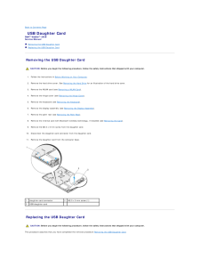
13 .Back to Contents Page US...Back to Contents Page USB Daughter CardDell™ Vostro™ 1510 Service Manual Removing the USB Daughter Card Replacing the USB Daughter Card Removing the USB Daughter Card CAUTION: Before you begin the following procedure, follow the safety instructions that...
-
14 .1. Replace the M2.5 x 5-m...1. Replace the M2.5 x 5-mm screw to secure the daughter card to the computer base.2. Connect the daughter card connector to the daughter card.3. Replace the internal card with Bluetooth wireless technology, if installed (see Removing the Card).4. Replace t...
-
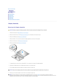
15 .Back to Contents Page Di...Back to Contents Page DisplayDell™ Vostro™ 1510 Service Manual Display Assembly Display Bezel Display Inverter Display Panel Display Cable Camera and Microphone Assembly Display Assembly Removing the Display Assembly CAUTION: Before you begin the fo...
-
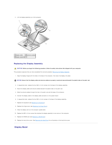
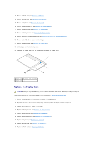
16 .11. Lift the display asse...11. Lift the display assembly out of the computer.1 display cable2 antenna cables3 display assembly Replacing the Display Assembly CAUTION: Before you begin the following procedure, follow the safety instructions that shipped with your computer.This pro...
-
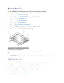
17 .Removing the Display Beze...Removing the Display Bezel CAUTION: Before you begin the following procedure, follow the safety instructions that shipped with your computer.1. Follow the instructions in Before Working on Your Computer.2. Remove the hard drive cover. See Removing the Hard...
-
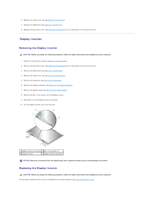
18 .6. Replace the hinge cove...6. Replace the hinge cover (see Replacing the Hinge Cover).7. Replace the WLAN card (see Replacing a WLAN Card).8. Replace the hard drive cover. See Removing the Hard Drive for an illustration of the hard drive cover. Display Inverter Removing the Display ...
-
19 .1. Connect the two displa...1. Connect the two display-inverter connectors to the display inverter.2. Replace the M2 x 3-mm screw that secures the display inverter.3. Replace the display bezel (seeReplacing the Display Bezel).4. Replace the display assembly (see Replacing the Display...
-
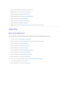
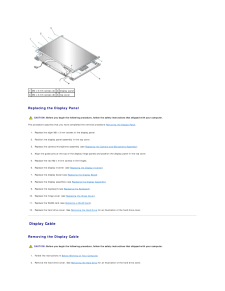
20 .1 M2 x 5-mm screws (2) 2 ...1 M2 x 5-mm screws (2) 2 display panel3 M2 x 3-mm screws (8) 4 top cover Replacing the Display Panel CAUTION: Before you begin the following procedure, follow the safety instructions that shipped with your computer.This procedure assumes that you have comp...
-
21 .3. Remove the WLAN card (...3. Remove the WLAN card (see Removing a WLAN Card).4. Remove the hinge cover (see Removing the Hinge Cover).5. Remove the keyboard (see Removing the Keyboard).6. Remove the display assembly (see Removing the Display Assembly).7. Remove the display bezel (s...
-
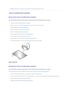
22 .10.Replace the hard drive...10.Replace the hard drive cover. See Removing the Hard Drive for an illustration of the hard drive cover. Camera and Microphone Assembly Removing the Camera and Microphone Assembly CAUTION: Before you begin the following procedure, follow the safety instru...
-
23 .5.Replace the keyboard (s...5.Replace the keyboard (see Replacing the Keyboard).6. Replace the hinge cover (see Replacing the Hinge Cover).7. Replace the WLAN card (see Replacing a WLAN Card).8. Replace the hard drive cover. See Removing the Hard Drive for an illustration of the hard...
-
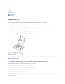
24 .Back to Contents Page Fa...Back to Contents Page FanDell™ Vostro™ 1510 Service Manual Removing the Fan Replacing the Fan Removing the Fan CAUTION: Before you begin the following procedure, follow the safety instructions that shipped with your computer.1. Follow the instructions i...
-
25 .25 ページ目のマニュアル
-
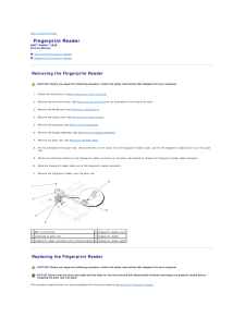
26 .Back to Contents Page Fi...Back to Contents Page Fingerprint ReaderDell™ Vostro™ 1510 Service Manual Removing the Fingerprint Reader Replacing the Fingerprint Reader Removing the Fingerprint Reader CAUTION: Before you begin the following procedure, follow the safety instructions ...
-
27 .1. Position the fingerpri...1. Position the fingerprint reader on the underside of the palm rest.2. Connect the fingerprint reader cable connector to the fingerprint reader connector and rotate the retaining bracket downward to secure the cable.3. Replace the fingerprint reader cover...
-
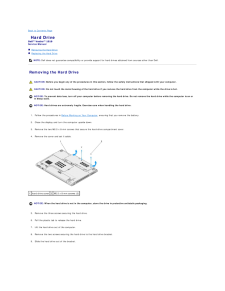
28 .Back to Contents Page Ha...Back to Contents Page Hard DriveDell™ Vostro™ 1510 Service Manual Removing the Hard Drive Replacing the Hard DriveNOTE: Dell does not guarantee compatibility or provide support for hard drives obtained from sources other than Dell. Removing the Hard Dri...
-
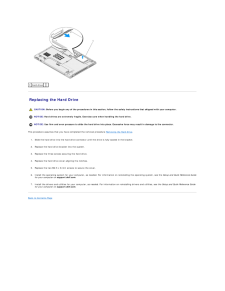
29 .1 hard drive Replacin...1 hard drive Replacing the Hard Drive CAUTION: Before you begin any of the procedures in this section, follow the safety instructions that shipped with your computer. NOTICE: Hard drives are extremely fragile. Exercise care when handling the hard drive...
-
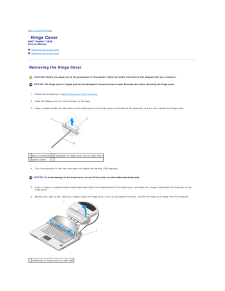
30 .Back to Contents Page Hi...Back to Contents Page Hinge CoverDell™ Vostro™ 1510 Service Manual Removing the Hinge Cover Replacing the Hinge Cover Removing the Hinge Cover CAUTION: Before you begin any of the procedures in this section, follow the safety instructions that shipped w...
-
31 .Replacing the Hinge Cove...Replacing the Hinge Cover CAUTION: Before you begin any of the procedures in this section, follow the safety instructions that shipped with your computer. NOTICE: The hinge cover is fragile and can be damaged if extreme force is used. Exercise care when r...
-
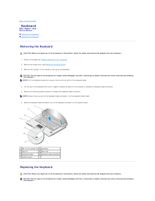
32 .Back to Contents Page Ke...Back to Contents Page KeyboardDell™ Vostro™ 1510 Service Manual Removing the Keyboard Replacing the Keyboard Removing the Keyboard CAUTION: Before you begin any of the procedures in this section, follow the safety instructions that shipped with your com...
-
33 .This procedure assumes th...This procedure assumes that you have completed the removal procedure Removing the Keyboard.1. Slide the keyboard cable connector into the keyboard connector. on the system board.2. Rotate the retaining bracket downward to secure the keyboard cable connecto...
-
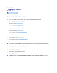
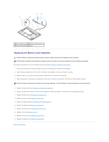
34 .Back to Contents Page Ba...Back to Contents Page Battery Latch AssemblyDell™ Vostro™ 1510 Service Manual Removing the Battery Latch Assembly Replacing the Battery Latch Assembly Removing the Battery Latch Assembly CAUTION: Before you begin the following procedure, follow the safe...
-
35 .1 battery release button ...1 battery release button 2 alignment bracket screw (1)3 battery latch assembly 4 spring Replacing the Battery Latch Assembly CAUTION: Before you begin the following procedure, follow the safety instructions that shipped with your computer. NOTICE: Ensure t...
-
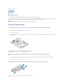
36 .Back to Contents Page Me...Back to Contents Page MemoryDell™ Vostro™ 1510 Service Manual Removing a Memory Module Replacing a Memory ModuleYour computer has two user-accessible SODIMM sockets, both accessed from the bottom of the computer.You can increase your computer memory by ...
-
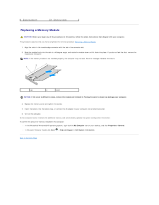
37 .1securing clips (2)2memor...1securing clips (2)2memory module Replacing a Memory Module CAUTION: Before you begin any of the procedures in this section, follow the safety instructions that shipped with your computer.This procedure assumes that you have completed the removal procedure...
-
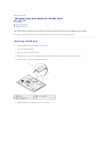
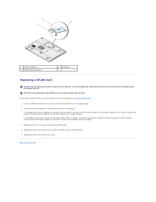
38 .Back to Contents Page Wi...Back to Contents Page Wireless Local Area Network (WLAN) CardDell™ Vostro™ 1510 Service Manual Removing a WLAN Card Replacing a WLAN Card CAUTION: Before you begin any of the procedures in this section, follow the safety instructions that shipped with y...
-
39 .1antenna cables (2)2WLAN ...1antenna cables (2)2WLAN card3system board connector Replacing a WLAN Card NOTICE: The connectors are keyed to ensure correct insertion. If you feel resistance, check the connectors on the card and on the system board,and realign the card. NOTICE: To avo...
-
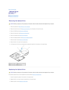
40 .Back to Contents Page Op...Back to Contents Page Optical DriveDell™ Vostro™ 1510 Service Manual Removing the Optical Drive Replacing the Optical Drive Removing the Optical Drive CAUTION: Before you begin any of the procedures in this section, follow the safety instructions that s...
-
41 .4. Replace the display as...4. Replace the display assembly (see Replacing the Display Assembly).5. Replace the keyboard (see Replacing the Keyboard).6. Replace the hinge cover (see Replacing the Hinge Cover).7. Replace the WLAN card (see Replacing a WLAN Card).8. Replace the hard dr...
-
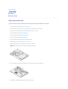
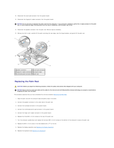
42 .Back to Contents Page Pa...Back to Contents Page Palm RestDell™ Vostro™ 1510 Service Manual Removing the Palm Rest Replacing the Palm Rest Removing the Palm Rest CAUTION: Before you begin the following procedure, follow the safety instructions that shipped with your computer.1. F...
-
43 .12. Disconnect the touch ...12. Disconnect the touch pad connector from the system board.13. Disconnect the fingerprint reader connector from the system board. NOTICE: Do not use force to separate the palm rest from the computer. If you encounter resistance, gently flex or apply pres...
-
44 .11.Replace the hinge cove...11.Replace the hinge cover (see Replacing the Hinge Cover).12. Replace the WLAN card (see Replacing a WLAN Card).13. Replace the hard drive cover. See Removing the Hard Drive for an illustration of the hard drive cover.14. Replace any blanks you removed fr...
-
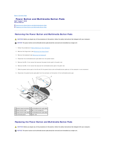
45 .Back to Contents Page Po...Back to Contents Page Power Button and Multimedia Button PadsDell™ Vostro™ 1510 Service Manual Removing the Power Button and Multimedia Button Pads Replacing the Power Button and Multimedia Button Pads Removing the Power Button and Multimedia Button Pad...
-
46 .This procedure assumes th...This procedure assumes that you have completed the removal procedure Removing the Power Button and Multimedia Button Pads.1. Connect the power-button pad cable in the connector on the bottom of the multimedia button pad.2. Slide the power button pad to the...
-
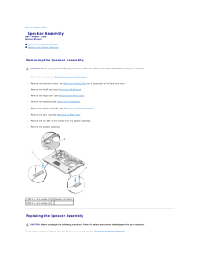
47 .Back to Contents Page Sp...Back to Contents Page Speaker AssemblyDell™ Vostro™ 1510 Service Manual Removing the Speaker Assembly Replacing the Speaker Assembly Removing the Speaker Assembly CAUTION: Before you begin the following procedure, follow the safety instructions that shi...
-
48 .1. Align the guide holds ...1. Align the guide holds in the speaker assembly with the guide posts on the base of the computer, then lower the assembly into place.2. Replace the four M2.5 x 5- mm screws to secure the speaker assembly3. Replace the palm rest (see Replacing the Palm Res...
-
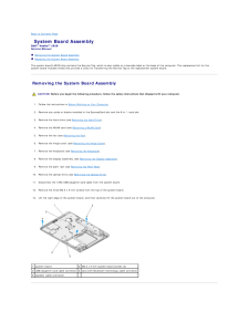
49 .Back to Contents Page Sy...Back to Contents Page System Board AssemblyDell™ Vostro™ 1510 Service Manual Removing the System Board Assembly Replacing the System Board AssemblyThe system board's BIOS chip contains the Service Tag, which is also visible on a barcode label on the bas...
-
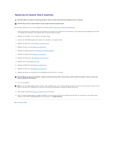
50 .Replacing the System Boa...Replacing the System Board Assembly CAUTION: Before you begin the following procedure, follow the safety instructions that shipped with your computer. NOTICE: Ensure that any loose cables do not get caught beneath the system board.This procedure assumes t...
-
51 .Back to Contents PageDell...Back to Contents PageDell™ Vostro™ 1510 Service ManualNOTE: A NOTE indicates important information that helps you make better use of your computer.NOTICE: A NOTICE indicates either potential damage to hardware or loss of data and tells you how to avoid the...
-
52 .Back to Contents Page Tr...Back to Contents Page TroubleshootingDell™ Vostro™ 1510 Service Manual Troubleshooting Tools Solving Problems Dell Technical Update Service Dell Support Utility Troubleshooting Tools Diagnostic Lights CAUTION: Before you begin any of the procedures in...
-
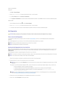
53 .resolve the incompatibili...resolve the incompatibility.Windows XP:1. Click Start® Help and Support.2. Type hardware troubleshooter in the search field and press
to start the search.3. In the Fix a Problem section, click Hardware Troubleshooter.4. In the Hardware Troubleshoot... -
54 .NOTE: It is recommended t...NOTE: It is recommended that you select Test System to run a complete test on your computer. Selecting Test Memory initiates the extendedmemory test, which can take up to thirty minutes or more to complete. When the test completes, record the test results ...
-
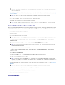
55 .After the Dell Diagnostic...After the Dell Diagnostics loads the following menu appears: OptionFunction Test Memory Run the stand-alone memory testTest SystemRun system diagnosticsExitExit the diagnosticsPress
to select the test you want to run and then press .NOTE: It ... -
56 .Windows XP:1.2.3.4. Click...Windows XP:1.2.3.4. Click Start® Control Panel® Add or Remove Programs® Programs and Features. Select the program you want to remove. Click Uninstall. See the program documentation for installation instructions.Windows Vista:1.2.3.4. Click Start® Control P...
-
57 .Test the drive — ll Inse...Test the drive — ll Insert another disc to eliminate the possibility that the original drive is defective. Insert a bootable floppy disk and restart the computer. Clean the drive or disk —For information on cleaning your computer, see the Dell™ Technology...
-
58 .1.2.3. Click Startand cli...1.2.3. Click Startand click Computer. Right-click Local Disk C:. Click Properties® Tools® Check Now.The User Account Control window may appear. If you are an administrator on the computer, click Continue; otherwise, contact your administrator tocontinue th...
-
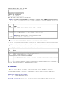
59 .A program stops respondin...A program stops responding End the program — 1.2.3.4. Press
simultaneously to access the Task Manager. Click the Applications tab. Click to select the program that is no longer responding. Click End Task. A program crashes repeatedlyNOTE... -
60 .Memory Problems CAUTION: ...Memory Problems CAUTION: Before you begin any of the procedures in this section, follow the safety instructions that shipped with your computer. If you receive an insufficient memory message — llll Save and close any open files and exit any open programs ...
-
61 .Check the headphone cabl...Check the headphone cable connection — Ensure that the headphone cable is securely inserted into the headphone connector. See the Setup and QuickReference Guide for your computer at support.dell.com. Adjust the Windows volume control — Click or double-cli...
-
62 .Accessing the Dell Suppor...Accessing the Dell Support UtilityAccess the Dell Support Utility from theicon on the taskbar or from the Start menu.If the Dell Support icon does not appear in your taskbar:1. Click Start® All Programs® Dell Support® Dell Support Settings.2. Ensure that t...
