
Vostro 2420の取扱説明書・マニュアル [全148ページ 4.05MB]


3


1 / 148 ページ
1 / 148 ページ


現在のページURL
DellTM PowerEdgeTM 2420Installation GuideGuide d'installationInstallationsanleitung設置ガイドGuia de instalacion
参考になったと評価  4人が参考になったと評価しています。


このマニュアルの目次
-
1 .DellTM PowerEdgeTM 2420In...DellTM PowerEdgeTM 2420Installation GuideGuide d'installationInstallationsanleitung設置ガイドGuia de instalacion
-
2 .2 ページ目のマニュアル
-
4 .Notes, Cautions, and Warn...Notes, Cautions, and Warnings NOTE: A NOTE indicates important informati on that helps you make better use of your computer. CAUTION: A CAUTION indicates potential dama ge to hardware or loss of data if instructions are not followed. WARNING: A WARNING...
-
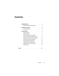
5 .Contents 3ContentsSafety ...Contents 3ContentsSafety Instructions . . . . . . . . . . . . . . . . . . . . . 5SAFETY: Rack Mounting of Systems . . . . . . . . . 5Installation Instructions. . . . . . . . . . . . . . . . . . 5Rack Requirements. . . . . . . . . . . . . . . . . . ...
-
7 .Installation Guide 5Safet...Installation Guide 5Safety InstructionsUse the following safety guidelines to ensure your own personal safety and to help protect your system and working environment from potential damage. For complete safety and regulatory in formation, see the safety in...
-
8 .6 Installation GuideRack ...6 Installation GuideRack Requirements CAUTION: The 24-U rack meets the sp ecifications of American National Standards Institute (ANSI)/Elec tronic Industries Association (EIA) standard ANSI/EIA-310-D-92, Consumer Electronic s Association (CEA) Standard C...
-
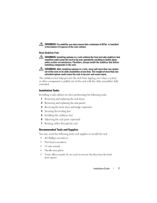
9 .Installation Guide 7 WARN...Installation Guide 7 WARNING: For stability, you must ensure that a minimum of 50 lbs. is installed in the bottom 3-U space s of the rack cabinet.Rack Stabilizer Feet WARNING: Installing systems in a rack withou t the front and side stabilizer feet inst...
-
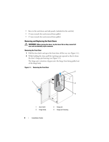
10 .8 Installation Guide Keys...8 Installation Guide Keys to the rack doors and side panels (included in the rack kit) 13-mm wrench (for rack removal from pallet) 17-mm wrench (for rack removal from pallet)Removing and Replacing the Rack Doors WARNING: When storing the doors, lay the ...
-
11 .Installation Guide 93 Whi...Installation Guide 93 While holding the hinge pin out of th e door's hinge-pin housing, pull the door slightly away from the rack so that the door clears the hinge body.4 Release the hinge pin.5 Lift the door upward so that th e door clears the bottom hin...
-
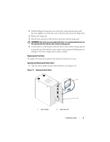
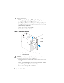
12 .10 Installation Guide2 Re...10 Installation Guide2 Remove the right door.a While supporting the door, pull the pin for the top hinge out of the door's hinge-pin housing (see Figure 1-3).You will hear a click as you pull the pin out of the door's hinge-pin housing. The hinge pins ar...
-
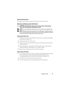
13 .Installation Guide 11Repl...Installation Guide 11Replacing the Back DoorsTo replace the back doors, perform the steps for removal in reverse. Removing and Replacing the Side Panels CAUTION: Reinstalling the side panels is nec essary before running systems in the rack to ensure prop...
-
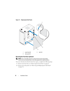
14 .12 Installation GuideFigu...12 Installation GuideFigure 1-4. Replacing the Side PanelsReversing the Front Door (optional) NOTE: Use a 4-mm Allen wrench to remove the front-door hinge bodies from the rack and reinstall them on the side opposi te their original positions.To reverse ...
-
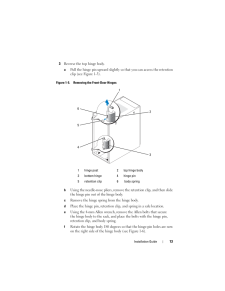
15 .Installation Guide 133 Re...Installation Guide 133 Reverse the top hinge body.a Pull the hinge pin upward slightly so that you can access the retention clip (see Figure 1-5).Figure 1-5. Removing the Front-Door HingesbUsing the needle-nose pliers, remove the retention clip, and then ...
-
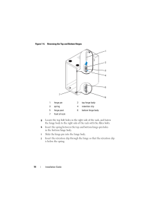
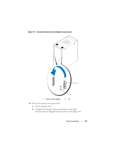
16 .14 Installation GuideFigu...14 Installation GuideFigure 1-6. Reversing the Top and Bottom HingesgLocate the top bolt holes in the ri ght side of the rack, and fasten the hinge body to the right side of the rack with the Allen bolts. h Insert the spring between the top and bottom hin...
-
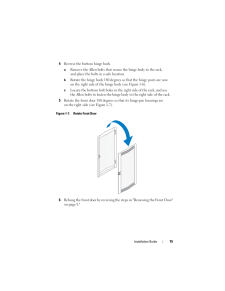
17 .Installation Guide 154 Re...Installation Guide 154 Reverse the bottom hinge body.a Remove the Allen bolts that secure the hinge body to the rack, and place the bolts in a safe location.b Rotate the hinge body 180 degrees so that the hinge posts are now on the right side of the hinge...
-
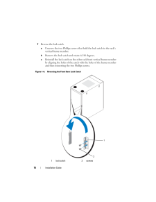
18 .16 Installation Guide7 Re...16 Installation Guide7 Reverse the lock catch.a Unscrew the two Phillips screws that hold the lock catch to the rack's vertical frame member.b Remove the lock catch and rotate it 180 degrees.c Reinstall the lock catch on the othe r rack front vertical fram...
-
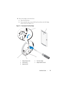
19 .Installation Guide 178 Re...Installation Guide 178 Reverse the badge on the front door.a Open the front door.b From inside the door, insert a flat -head screwdriver into the badge release notch (see Figure 1-9).Figure 1-9. Reversing the Front Door Badge1 badge release notch 2 front ...
-
20 .18 Installation Guidec Pu...18 Installation Guidec Push the screwdriver into the notch until it stops and turn it counter-clockwise.d Lift up on the badge and pull it off the door.e Rotate the badge 180 degrees so that it will read correctly when reinstalled.f Locate the fourth hori...
-
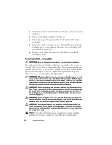
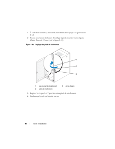
21 .Installation Guide 191 Us...Installation Guide 191 Using a screwdriver, lower the leveling foot until it rests on the floor.2 If you need to lower the foot furt her, tighten the hex nut clockwise with a 12-mm wrench (see Figure 1-10).Figure 1-10. Adjusting the Leveling Feet3 Repeat ...
-
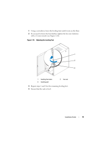
22 .20 Installation GuideInst...20 Installation GuideInstalling the Rack Stabilizer Feet WARNING: Installing systems in a rack withou t the front and side stabilizer feet installed could cause the ra ck to tip over, potentially resulting in bodily injury under certain circumstances. Th...
-
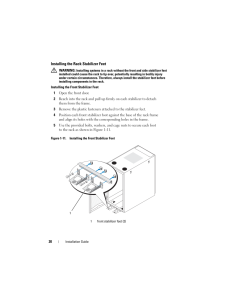
23 .Installation Guide 21Inst...Installation Guide 21Installing the Side Stabilizer Feet1 Remove the side panel.2 On the side of the rack frame's bottom rail, locate the four holes (see Figure 1-12).3 Position each stabilizer foot against the base of the rack frame and align its holes ...
-
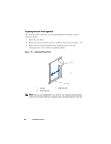
24 .22 Installation GuideAdju...22 Installation GuideAdjusting the Rack Posts (optional)The position of the rack posts can be adjusted to accommodate systems of various depths. 1Open the rack doors. 2 Remove the screws from the bottom and top of the post (see Figure 1-13).3 Move the po...
-
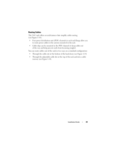
25 .Installation Guide 23Rout...Installation Guide 23Routing CablesThe 24-U rack offers several featur es that simplify cable routing (see Figure 1-14). Four power distribution unit (PDU) cha nnels in each rack flange allow you to route power cables to the systems mounted in the rack. C...
-
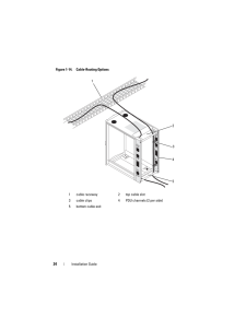
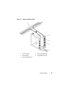
26 .24 Installation GuideFigu...24 Installation GuideFigure 1-14. Cable-Routing Options1 cable raceway 2 top cable slot3 cable clips 4 PDU channels (2 per side)5 bottom cable exit12453
-
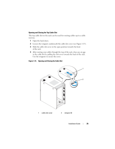
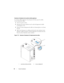
27 .Installation Guide 25Open...Installation Guide 25Opening and Closing the Top Cable SlotThe top cable slot in the rack can be used for routing cables up to a cable raceway.1Open the back doors.2 Loosen the wingnuts underneath the cable slot cover (see Figure 1-15).3 Slide the cable s...
-
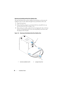
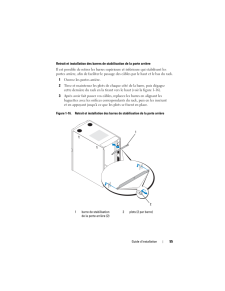
28 .26 Installation GuideRemo...26 Installation GuideRemoving and Installing the Back Door Stabilizer BarsThe top and bottom bars used to stabi lize the back doors can be removed, making it easier to route cables thro ugh the top and bottom of the rack.1Open the back doors.2 Pull and ho...
-
29 .Index 27IndexBback doorop...Index 27IndexBback dooropening, 9removing, 10Ccablesrouting, 23Ddoorsremoving, 8Ffront doorremoving, 8-9reversing, 12Lleveling feet, 18Rrack stabilizer feet, 7, 20routing cables, 23Ssafety instructions, 5side panelsremoving, 11Ttools and supplies, 7
-
32 .Remarques, precautions et...Remarques, precautions et avertissements REMARQUE : Une REMARQUE indique des informa tions importantes qui peuvent vous aider a mieux utiliser votre ordinateur. PRECAUTION : Une PRECAUTION vous avertit d' un risque de dommage materiel ou de perte de donn...
-
33 .Table des matieres 31Tabl...Table des matieres 31Table des matieresConsignes de securite . . . . . . . . . . . . . . . . . . 33SECURITE : montage en rack des systemes . . . . 33Instructions d'installation. . . . . . . . . . . . . . . . 33Exigences du rack . . . . . . . . . ....
-
35 .Guide d'installation 33Co...Guide d'installation 33Consignes de securiteRespectez les consignes de securite de ce guide pour assurer votre securite personnelle et pour contribuer a prot eger le systeme et l'environnement de travail de dommages potentiels. Pour obtenir des informati...
-
36 .34 Guide d'installationEx...34 Guide d'installationExigences du rack PRECAUTION : Le rack 24U est conforme a ux specifications des organismes suivants : norme ANSI/EIA-310-D- 92 de l'American National Standards Institute (ANSI)/Electronic Industries Association (EIA), norme CEA-3...
-
37 .Guide d'installation 35In...Guide d'installation 35Informations importantes concernant la securiteRespectez les consignes de securite decr ites dans les sous-sections suivantes lors de l'installation du systeme dans le rack. AVERTISSEMENT : Vous devez respecter a la le ttre les proc...
-
38 .36 Guide d'installationOu...36 Guide d'installationOutils et fournitures recommandesPour installer le rack, vous pourrez av oir besoin des outils et fournitures suivants : Tournevis cruciforme n2 Tournevis a tete plate Cle de 12 mm Pince a bec fin Cle Allen de 4 mm (si vous souhaitez...
-
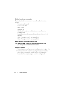
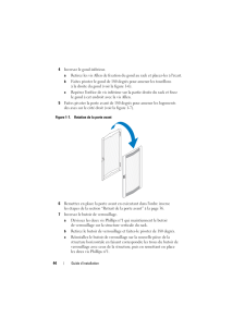
39 .Guide d'installation 37Fi...Guide d'installation 37Figure 1-1. Retrait de la porte avant3 Tout en maintenant l'axe du gond ho rs du logement, tirez legerement la porte du rack pour la degager du logement.4 Lachez l'axe du gond.5 Soulevez la porte pour la degager du gond inferieur. AV...
-
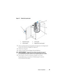
40 .38 Guide d'installationRe...38 Guide d'installationRemise en place de la porte avantPour remettre en place la porte avan t, procedez a l'inverse du retrait. Ouverture et retrait des portes arriere1 Tournez la poignee et ouvrez les po rtes arriere (voir la figure 1-2).Figure 1-2. Ouve...
-
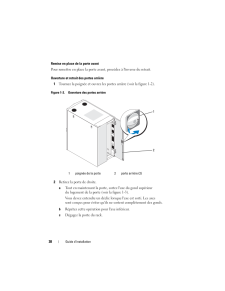
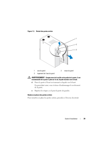
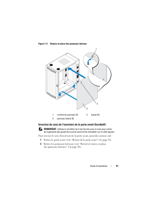
41 .Guide d'installation 39Fi...Guide d'installation 39Figure 1-3. Retrait des portes arriere AVERTISSEMENT : Compte tenu de la taille et du po ids de la porte, il est recommande de la poser a plat sur le sol, facade tournee vers le haut.dPosez la porte a l'ecart en tournant sa facade...
-
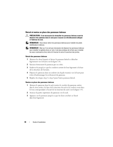
42 .40 Guide d'installationRe...40 Guide d'installationRetrait et remise en place des panneaux lateraux PRECAUTION : Il est necessaire de reinstaller les panneaux lateraux avant de demarrer des systemes dans le rack po ur s'assurer un refroidissement adequat a l'interieur du rack. REMA...
-
43 .Guide d'installation 41Fi...Guide d'installation 41Figure 1-4. Remise en place des panneaux laterauxInversion du sens de l'ouverture de la porte avant (facultatif) REMARQUE : Utilisez la cle Allen de 4 mm fou rnie avec le rack pour retirer les logements des gonds de la porte avant ...
-
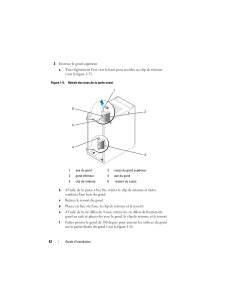
44 .42 Guide d'installation3 ...42 Guide d'installation3 Inversez le gond superieur.a Tirez legerement l'axe vers le haut pour acceder au clip de retenue (voir la figure 1-5).Figure 1-5. Retrait des axes de la porte avantbA l'aide de la pince a bec fin, reti rez le clip de retenue et fa...
-
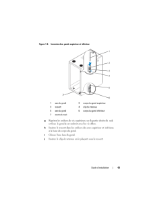
45 .Guide d'installation 43Fi...Guide d'installation 43Figure 1-6. Inversion des gonds superieur et inferieurgReperez les orifices de vis superieurs sur la partie droite du rack et fixez le gond a cet endroit avec les vis Allen. h Inserez le ressort dans les orifices des axes superieur ...
-
46 .44 Guide d'installation4 ...44 Guide d'installation4 Inversez le gond inferieur.a Retirez les vis Allen de fixation du gond au rack et placez-les a l'ecart.b Faites pivoter le gond de 180 d egres pour amener les tourillons a la droite du gond (voir la figure 1-6).c Reperez l'orifice...
-
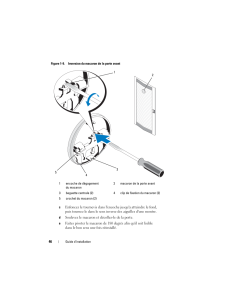
47 .Guide d'installation 45Fi...Guide d'installation 45Figure 1-8. Inversion du buto ir de verrouillage de la porte avant8 Inversez le macaron sur la porte avant.a Ouvrez la porte avant.b A l'interieur de la porte, inserez un tournevis a tete plate dans l'encoche de degagement du macaron...
-
48 .46 Guide d'installationFi...46 Guide d'installationFigure 1-9. Inversion du macaron de la porte avantcEnfoncez le tournevis dans l'en coche jusqu'a atteindre le fond, puis tournez le dans le sens inverse des aiguilles d'une montre.d Soulevez le macaron et decollez-le de la porte.e Fa...
-
49 .Guide d'installation 47f ...Guide d'installation 47f Identifiez la quatrieme barre horizontale a partir du haut de la porte et faites glisser les crochets du macaron dessus, en alignant les baguettes centrales du macaron sur la barre verticale sur la porte.g Appuyez sur les clips de ...
-
50 .48 Guide d'installation1 ...48 Guide d'installation1 A l'aide d'un tournevis, abaissez le pied stabilisateur jusqu'a ce qu'il touche le sol.2 Si vous avez besoin d'abaisser davantage le pied, resserrez l'ecrou 6 pans a l'aide d'une cle 12 mm (voir la figure 1-10).Figure 1-10. Reglage...
-
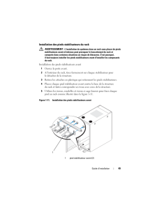
51 .Guide d'installation 49In...Guide d'installation 49Installation des pieds stabilisateurs du rack AVERTISSEMENT : L'installation de systemes dans un rack sans placer de pieds stabilisateurs avant et lateraux peut provoquer le basculement du rack et comporte dans certaines situation...
-
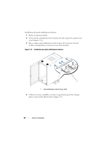
52 .50 Guide d'installationIn...50 Guide d'installationInstallation des pieds stabilisateurs lateraux1 Retirez le panneau lateral.2 Sur le cote du rail inferieur de la structure du rack, reperez les quatre trous (voir la figure 1-12).3 Placez chaque pied stabilisateur contre la base de ...
-
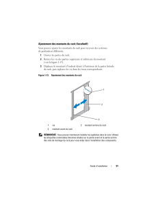
53 .Guide d'installation 51Aj...Guide d'installation 51Ajustement des montants du rack (facultatif)Vous pouvez ajuster les montants du rack pour recevoir des systemes de profondeur differente. 1 Ouvrez les portes du rack. 2 Retirez les vis des parties superieure et inferieure du montant...
-
54 .52 Guide d'installationAc...52 Guide d'installationAcheminement des cablesLe rack 24U dispose de plusieurs elemen ts qui simplifient le routage des cables (voir la figure 1-14). Quatre canaux d'unite de distribution de l'alimentation (PDU) presents dans chaque plaque permettent de fa...
-
55 .Guide d'installation 53Fi...Guide d'installation 53Figure 1-14. options de routage des cables1 chemin de cables 2 fente de cable superieure3 clips de cables 4 cana ux PDU (2 par cote)5 sortie de cable inferieure12453
-
56 .54 Guide d'installationOu...54 Guide d'installationOuverture et fermeture de la sortie de cable superieureLa sortie de cable superieure du rack permet de faire passer les cables vers un chemin de cables.1 Ouvrez les portes arriere.2 Desserrez les ecrous a ailettes sous le cache du ...
-
57 .Guide d'installation 55Re...Guide d'installation 55Retrait et installation des barres de stabilisation de la porte arriereIl est possible de retirer les barres su perieure et inferieure qui stabilisent les portes arriere, afin de faciliter le passa ge des cables par le haut et le ba...
-
59 .Index 57IndexCCablesrouta...Index 57IndexCCablesroutage, 52Consignes de securite, 33Couvercle arriereouverture, 38retrait, 38Couvercle avantinversion, 41retrait, 36, 38OOutils et fournitures, 36PPanneaux laterauxretrait, 40pieds de mise de niveau, 47Portesretrait, 36RRack, pieds stab...
-
62 .Anmerkungen, Vorsichtshin...Anmerkungen, Vorsichtshinweise und Warnungen ANMERKUNG: Eine ANMERKUNG macht auf wichtige Informationen aufmerksam, mit denen Sie das System besser einsetzen konnen. VORSICHT: Hiermit werden Sie auf mogl iche Gefahrenquellen hingewiesen, die Hardwaresch...
-
63 .Inhalt 61InhaltSicherheit...Inhalt 61InhaltSicherheitshinweise . . . . . . . . . . . . . . . . . . . 63SICHERHEIT: Systeme im Rack montieren . . . . . 63Installationsanleitung. . . . . . . . . . . . . . . . . . 64Rackanforderungen . . . . . . . . . . . . . . . . 64Rackins...
-
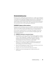
65 .Installationsanleitung 63...Installationsanleitung 63SicherheitshinweiseBeachten Sie die nachfolgenden Sicherheitshinweise, um Ihre eigene Sicherheit zu gewahrleisten und eine Beschadigung des Systems und der Arbeitsumgebung zu vermeiden. Die vollstandigen wich tigen Informationen zu...
-
66 .64 Installationsanleitung...64 InstallationsanleitungInstallationsanleitungDiese Installationsanleitung enthalt Anweisungen fur geschulte Servicetechniker zur Installation eines 24-U-Racks (Rack mit 24 Einheiten). Sie erfahren unter anderem, wie Sie das Rack montieren und Kabel du...
-
67 .Installationsanleitung 65...Installationsanleitung 65Wichtige SicherheitshinweiseBeachten Sie beim Einbau des Systems im Rack die Sicherheitsmanahmen in den folgenden Unterabschnitten. WARNUNG: Befolgen Sie die in diesem Dokument angegebenen Vorgehensweisen genau, um sich selbst un...
-
68 .66 Installationsanleitung...66 InstallationsanleitungEmpfohlene Werkzeuge und ZubehorFur die Installation des Racks benoti gen Sie eventuell folgende Werkzeuge und Zubehorteile: Kreuzschlitzschraubendreher Groe 2 Senkkopfschraubendreher 12-mm-Schraubenschlussel Spitzzange 4-mm-Inbuss...
-
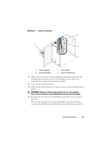
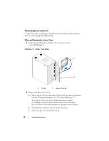
69 .Installationsanleitung 67...Installationsanleitung 67Abbildung 1-1. Vordere Tur entfernen3 Halten Sie den aus dem Scharniersti ftgehause gezogenen Scharnierstift weiterhin fest und ziehen Sie die Tur vorsichtig von dem Rack weg, sodass die Tur aus dem Scharniergehause gleitet.4 Lass...
-
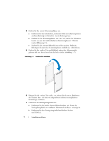
70 .68 Installationsanleitung...68 InstallationsanleitungWiederanbringen der vorderen TurUm die Tur wieder anzubringen, wieder holen Sie die Schritte zum Entfernen der Tur in der umgekehrten Reihenfolge. Offnen und Abnehmen der hinteren Turen1 Drehen Sie den Turgriff und of fnen Sie die ...
-
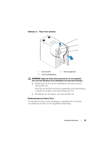
71 .Installationsanleitung 69...Installationsanleitung 69Abbildung 1-3. Hintere Turen abnehmen WARNUNG: Wegen der Groe und des Gewi chts der Tur wird empfohlen, diese nach dem Abnehmen mit der Au enflache nach oben flach hinzulegen.dBewahren Sie die Tur mit der Auenflache nach oben an e...
-
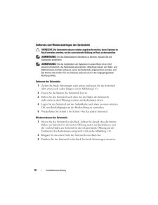
72 .70 Installationsanleitung...70 InstallationsanleitungEntfernen und Wiederanbringen der Seitenteile VORSICHT: Die Seitenteile mussen wieder angebr acht werden, bevor Systeme im Rack betrieben werden, um die ausreichende Kuhlung im Rack sicherzustellen. ANMERKUNG: Um die Stabilisat...
-
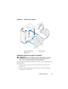
73 .Installationsanleitung 71...Installationsanleitung 71Abbildung 1-4. Seitenteile wieder anbringenUmgekehrtes Einbauen der vorderen Tur (optional) ANMERKUNG: Nehmen Sie mithilfe eines 4-mm- Inbusschlussel die Scharnier-gehause der vorderen Tur vom Rack ab . Montieren Sie die Gehause d...
-
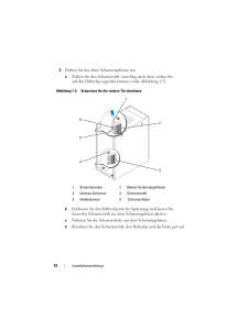
74 .72 Installationsanleitung...72 Installationsanleitung3 Drehen Sie das obere Scharniergehause um.a Ziehen Sie den Scharnierstift vorsichtig nach oben, sodass Sie auf den Halteclip zugreifen konnen (siehe Abbildung 1-5).Abbildung 1-5. Scharniere fur die vordere Tur abnehmenbEntfernen ...
-
75 .Installationsanleitung 73...Installationsanleitung 73e Entfernen Sie mit einem 4-mm-Inbusschlussel die Inbusbolzen, mit deren Hilfe das Scharniergehause am Rack befestigt ist. Bewahren Sie die Bolzen zusammen mit dem Scharnierstift, dem Halteclip und der Scharnierfeder auf.f Drehen S...
-
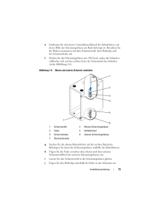
76 .74 Installationsanleitung...74 Installationsanleitung4 Drehen Sie das untere Scharniergehause um.a Entfernen Sie die Inbusbolzen, mit deren Hilfe das Scharniergehause am Rack befestigt ist. Bewahren Sie die Bolzen gut auf.b Drehen Sie das Scharniergehause um 180 Grad, sodass die Sch...
-
77 .Installationsanleitung 75...Installationsanleitung 75c Bringen Sie den Verriegelungshebel wieder am vertikalen Rahmenteil des anderen Racks an. Richten Sie dabei die Locher der Verriegelung nach den Lochern am Rahmen aus und bringen Sie die zwei Kreuz-schlitzschrauben wieder an.Abb...
-
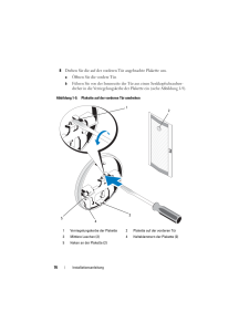
78 .76 Installationsanleitung...76 Installationsanleitung8 Drehen Sie die auf der vorderen Tur angebrachte Plakette um.a Offnen Sie die vordere Tur.b Fuhren Sie von der Innenseite der Tur aus einen Senkkopfschrauben-dreher in die Verriegelungskerbe de r Plakette ein (siehe Abbildung 1-9)...
-
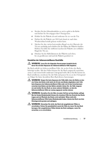
79 .Installationsanleitung 77...Installationsanleitung 77c Stecken Sie den Schraubendreher so weit es geht in die Kerbe und drehen Sie ihn entgegen dem Uhrzeigersinn.d Hebeln Sie die Plakette ab und entfernen Sie sie von der Tur.e Drehen Sie die Plakette um 180 Grad, damit sie nach dem ...
-
80 .78 Installationsanleitung...78 Installationsanleitung WARNUNG: Vor dem Installieren Ihrer Syst eme sollten Sie grundsatzlich das Rack ausrichten und die Stabilisatoren b efestigen. Ein voll beladenes Rack konnte umkippen, wenn es auf e inem unebenen Untergrund steht und das Gewicht...
-
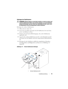
81 .Installationsanleitung 79...Installationsanleitung 79Anbringen der Stabilisatoren WARNUNG: Werden Systeme in einem Rack insta lliert, an dem die vorderen und seitlichen Stabilisatoren fehlen, kann das Rack umkipp en, was unter Umstanden schwere Verletzungen nach sich ziehen ka nn. ...
-
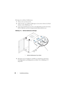
82 .80 Installationsanleitung...80 InstallationsanleitungBefestigen der seitlichen Stabilisatoren1 Nehmen Sie das Seitenteil ab.2 Suchen Sie die vier seitlichen Offnungen in der unteren Schiene des Rack-rahmens (siehe Abbildung 1-12).3 Legen Sie die Stabilisatoren jeweils vor den Rackrah...
-
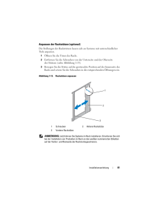
83 .Installationsanleitung 81...Installationsanleitung 81Anpassen der Rackstutzen (optional)Die Stellungen der Rackstutzen lassen sich an Systeme mit unterschiedlicher Tiefe anpassen. 1 Offnen Sie die Turen des Racks. 2 Entfernen Sie die Schrauben von der Unterseite und der Oberseite der...
-
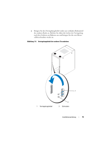
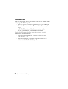
84 .82 Installationsanleitung...82 InstallationsanleitungVerlegen der KabelDas 24-U-Rack verfugt uber verschiedene Merkmale fur eine einfache Kabel-verlegung (siehe Abbildung 1-14). Durch vier Stromverteilerrohren (PDU-Rohren) in jedem Rackflansch konnen die Stromkabel zu den im Rack i...
-
85 .Installationsanleitung 83...Installationsanleitung 83Abbildung 1-14. Optionen fur die Kabelfuhrung1 Kabelkanal 2 Oberer Kabelschlitz3 Kabelklemmen 4 PDU-Rohren (2 pro Seite)5 Unterer Kabelausgang12453
-
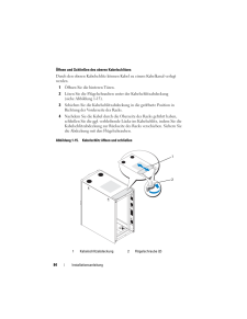
86 .84 Installationsanleitung...84 InstallationsanleitungOffnen und Schlieen des oberen KabelschlitzesDurch den oberen Kabelschlitz konnen Kabel zu einem Kabelkanal verlegt werden.1 Offnen Sie die hinteren Turen.2 Losen Sie die Flugelschrauben unter der Kabelschlitzabdeckung (siehe Abbil...
-
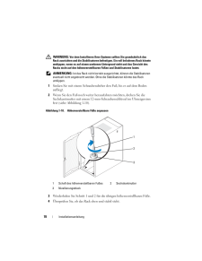
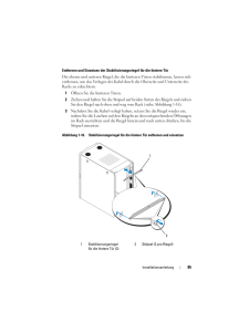
87 .Installationsanleitung 85...Installationsanleitung 85Entfernen und Einsetzen der Stabilis ierungsriegel fur die hintere TurDie oberen und unteren Riegel, die die hinteren Turen stabilisieren, lassen sich entfernen, um das Verlegen der Kabel dur ch die Oberseite und Unterseite des Rac...
-
89 .Stichwortverzeichnis 87St...Stichwortverzeichnis 87StichwortverzeichnisHHintere Turentfernen, 68offnen, 68Hohenverstellbare Fue, 77KKabelverlegen, 82Kabel verlegen, 82RRack-Stabilisierungs-standfue, 65, 79SSeitenteileentfernen, 70Sicherheitshinweise, 63TTurenentfernen, 66VVordere Tur...
-
92 .メモ、注意、警告 メモ: コンピュータを使いやすく...メモ、注意、警告 メモ: コンピュータを使いやすくするための重要な情報を説明しています。 注意: 手順に従わない場合は、ハードウ ェアの損傷やデータの損失の可能性があることを示しています。 警告: 物的損害、けがまたは死亡の原因となる可能性があることを示します。____________________本書の内容は予告なく変更されることがあります。(C) 2008 すべての著作権は Dell Inc. にあります。Dell Inc. の書面による許可のない複製は、いかなる形態においても厳重に禁じられていま...
-
93 .目次 91目次安全にお使いいただくために . ....目次 91目次安全にお使いいただくために . . . . . . . . . . . . 93安全について:システムのラックへの取り付け . . . . . . . . . . . . . . . . . 93取り付け手順. . . . . . . . . . . . . . . . . . . . . . 93ラックの要件. . . . . . . . . . . . . . . . . . . 94ラックへの取り付け . . . . . . . . . . . . . . . ...
-
95 .設置ガイド 93安全にお使いいただくためにご自身の...設置ガイド 93安全にお使いいただくためにご自身の身体の安全を守り、システムおよび作業環境を保護するために、以下の安全に関するガイドラインに従ってください。安全および認可機関に関する詳細情報は、システムに付属しているマニュアルの安全にお使いいただくための注意事項を参照してください。保証に関する情報は、『サービス&サポートのご案内』を参照してください。安全について:システムのラックへの取り付けラックの安定性や安全性に関して、以下の点にご注意ください。また、特定の注意文および手順については、システムおよびラック...
-
96 .94 設置ガイドラックの要件 注意: 24U ...94 設置ガイドラックの要件 注意: 24U ラックは、米国規格協会( ANSI)/米国電子工業会(EIA)規格 ANSI/ EIA-310-D-92、全米家電協会(CEA)規格 CEA-310-E、国際電気標準会議(IEC)規格 297、ドイツ工業規格(DIN)41494 に適合しています。ラックへの取り付け以下の取り付けを開始する前に、手順を最後までよくお読みください。作業を開始する前に 警告: ラックへの取り付け作業を開始する前に、 「安全に関する重要な注意」、およびラックに付属しているガイドの...
-
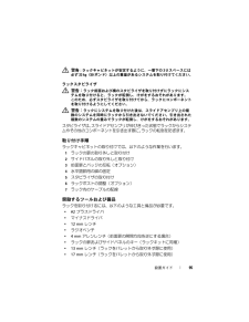
97 .設置ガイド 95 警告: ラックキャビネットが安...設置ガイド 95 警告: ラックキャビネットが安定するように、一番下の 3 U スペースには必ず 23 kg(50 ポンド)以上の重量があるシステムを取り付けてください。ラックスタビライザ 警告: ラック前面および横のスタビライザを取り付けずにラックにシステムを取り付けると、ラックが転倒し 、けがをするおそれがあります。このため、必ずスタビライザを取り 付けてから、ラックにコンポーネントを取り付けるようにしてください。 警告: ラックにシステムを取り付けた後は 、スライドアセンブリ上の複数のシステムを...
-
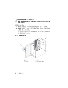
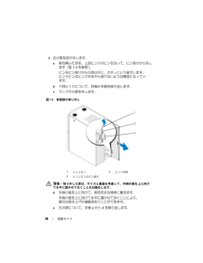
98 .96 設置ガイドラックの扉の取り外しと取り付け 警...96 設置ガイドラックの扉の取り外しと取り付け 警告: 扉を保管する際には、不意に倒れてけがをしないように水平に寝かせておきます。前面扉の取り外し1 扉のラッチを引き、前面扉を完全に開きます(図 1-1 を参照)。2 扉を開けたまま、上部ヒンジピンを上に引き、扉のピン受けから外します(図1-1 を参照)。ヒンジピンには固定クリップがあるため、ヒンジがヒンジ本体から外れることはありません。図1-1前面扉の取り外し1扉のラッチ2ヒンジピン3ヒンジ本体4ヒンジピンのピン受け4231
-
99 .設置ガイド 973 ヒンジピンをピン受けから引き出...設置ガイド 973 ヒンジピンをピン受けから引き出した状態で、扉をラックから少し手前に引き、ヒンジ本体から外します。4 ヒンジピンを元に戻します。5 扉を持ち上げ、下部のヒンジ軸を外します。 警告: 取り外した扉は、サイズと重量を考慮して、外側の面を上に向けて水平に寝かせておくことをお勧めします。6外側の面を上に向けて、扉を安全な場所に置きます。外側の面を上に向けて水平に寝かせておくことにより、扉のバッジと化粧仕上げの損傷を防ぐことができます。前面扉の取り付け前面扉を取り付ける場合は、取り外し手順を逆の順...
-
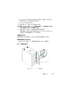
100 .98 設置ガイド2 右の扉を取り外します。a 扉を...98 設置ガイド2 右の扉を取り外します。a 扉を開いたまま、上部ヒンジのピンを引いて、ピン受けから外します(図1-3 を参照)。ピンをピン受けから引き出すと、 カチッという音がします。ヒンジピンはヒンジ本体から抜けないような構造になっています。b 下部ヒンジについて、同様の手順を 繰り返します。c ラックから扉を外します。図1-3背面扉の取り外し 警告: 取り外した扉は、サイズと重量を考慮して、外側の面を上に向けて水平に寝かせておくことをお勧めします。d外側の面を上に向けて、扉を安全な場所に置きます。外...
