
Inspiron Zinoの取扱説明書・マニュアル [全53ページ 1.08MB]


2


1 / 53 ページ
1 / 53 ページ


現在のページURL
Dell™ Inspiron™ 300/400 Service Manual Technical OverviewBefore You BeginTop CoverBottom CoverTop BracketI/O BezelOptical DriveDrive BayPower-Button BracketCoin-Cell BatteryHard DriveWireless Mini-Card (Inspiron 400 Only)Memory Module(s)Processor Heat Sink (Inspiron 400 Only)Processor (Inspiron 400 Only)Chassis FanI/O BracketGraphics-Card Heat Sink (Inspiron 400 Only)Graphics Card (Inspiron 400 Only)Graphics-Card Fan (Inspiron 400 Only)System BoardSystem Setup Utility Notes, Cautions, and WarningsNOTE: A NOTE indicates important information that helps you make better use of your computer.CAUTION: A CAUTION indicates either potential damage to hardware or loss of data and tells you how to avoid the problem.WARNING: A WARNING indicates a potential for property damage, personal injury, or death.Information in this document is subject to change without notice.© 2009 Dell Inc. All rights reserved.Reproduction of these materials in any manner whatsoever without the written permission of Dell Inc. is strictly forbidden.Trademarks used in this text: Dell, the DELL logo, and Inspiron are trademarks of Dell Inc.; Microsoft, Windows, Windows Vista, and Windows Vista start button logo are eithertrademarks or registered trademarks of Microsoft Corporation in the United States and/or other countries.Other trademarks and trade names may be used in this document to refer to either the entities claiming the marks and names or their products. Dell Inc. disclaims anyproprietary interest in trademarks and trade names other than its own.Regulatory Model D02U series Regulatory Type D02U001 and D02U002September 2009 Rev. A00
参考になったと評価  2人が参考になったと評価しています。
このマニュアルの目次
-
1 .Dell™ Inspiron™ 300/400 S...Dell™ Inspiron™ 300/400 Service Manual Technical OverviewBefore You BeginTop CoverBottom CoverTop BracketI/O BezelOptical DriveDrive BayPower-Button BracketCoin-Cell BatteryHard DriveWireless Mini-Card (Inspiron 400 Only)Memory Module(s)Processor Heat Sink...
-
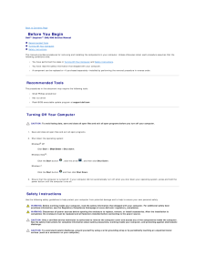
2 .Back to Contents Page Be...Back to Contents Page Before You BeginDell™ Inspiron™ 300/400 Service Manual Recommended Tools Turning Off Your Computer Safety InstructionsThis manual provides procedures for removing and installing the components in your computer. Unless otherwise n...
-
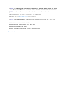
3 .CAUTION: When you disconn...CAUTION: When you disconnect a cable, pull on its connector or on its pull-tab, not on the cable itself. As you pull connectors apart, keep themevenly aligned to avoid bending any connector pins. Also, before you connect a cable, ensure that both connector...
-
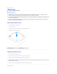
4 .Back to Contents Page Bo...Back to Contents Page Bottom CoverDell™ Inspiron™ 300/400 Service Manual Removing the Bottom Cover Replacing the Bottom CoverWARNING: Before working inside your computer, read the safety information that shipped with your computer. For additional safet...
-
5 .5 ページ目のマニュアル
-
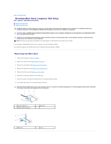
6 .Back to Contents Page Wi...Back to Contents Page Wireless Mini-Card (Inspiron 400 Only)Dell™ Inspiron™ 300/400 Service Manual Removing the Mini-Card Replacing the Mini-CardWARNING: Before working inside your computer, read the safety information that shipped with your computer. ...
-
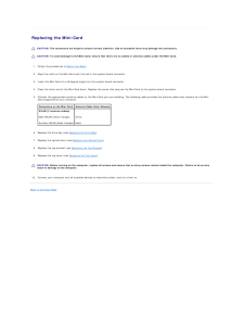
7 .Replacing the Mini-Card ...Replacing the Mini-Card CAUTION: The connectors are keyed to ensure correct insertion. Use of excessive force may damage the connectors. CAUTION: To avoid damage to the Mini-Card, ensure that there are no cables or antenna cables under the Mini-Card.1. Fo...
-
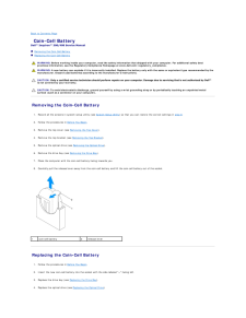
8 .Back to Contents Page Co...Back to Contents Page Coin-Cell BatteryDell™ Inspiron™ 300/400 Service Manual Removing the Coin-Cell Battery Replacing the Coin-Cell BatteryWARNING: Before working inside your computer, read the safety information that shipped with your computer. For a...
-
9 .5. Replace the top bracke...5. Replace the top bracket (see Replacing the Top Bracket).6. Replace the top cover (see Replacing the Top Cover). CAUTION: Before turning on the computer, replace all screws and ensure that no stray screws remain inside the computer. Failure to do so mayr...
-
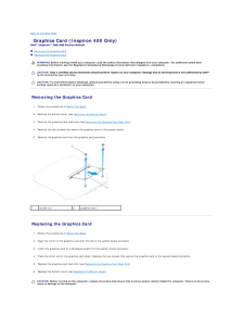
10 .Back to Contents Page Gr...Back to Contents Page Graphics Card (Inspiron 400 Only)Dell™ Inspiron™ 300/400 Service Manual Removing the Graphics Card Replacing the Graphics CardWARNING: Before working inside your computer, read the safety information that shipped with your compute...
-
11 .7. Connect your computer ...7. Connect your computer and all attached devices to electrical outlets, and turn them on.Back to Contents Page
-
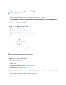
12 .Back to Contents Page Gr...Back to Contents Page Graphics-Card Fan (Inspiron 400 Only)Dell™ Inspiron™ 300/400 Service Manual Removing the Graphics-Card Fan Replacing the Graphics-Card FanWARNING: Before working inside your computer, read the safety information that shipped with ...
-
13 .13 ページ目のマニュアル
-
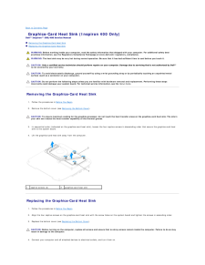
14 .Back to Contents Page Gr...Back to Contents Page Graphics-Card Heat Sink (Inspiron 400 Only)Dell™ Inspiron™ 300/400 Service Manual Removing the Graphics-Card Heat Sink Replacing the Graphics-Card Heat SinkWARNING: Before working inside your computer, read the safety information ...
-
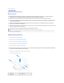
16 .Back to Contents Page Ha...Back to Contents Page Hard DriveDell™ Inspiron™ 300/400 Service Manual Removing the Hard Drive Replacing the Hard DriveWARNING: Before working inside your computer, read the safety information that shipped with your computer. For additional safety best...
-
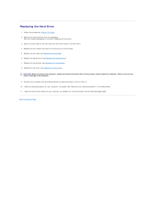
17 .Replacing the Hard Drive...Replacing the Hard Drive1.2. Follow the procedures in Before You Begin. Remove the new hard drive from its packaging.Save the original packaging for storing or shipping the hard drive.3. Align the screw holes on the drive bay with the screw holes on the h...
-
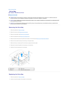
18 .Back to Contents Page Dr...Back to Contents Page Drive BayDell™ Inspiron™ 300/400 Service Manual Removing the Drive Bay Replacing the Drive BayWARNING: Before working inside your computer, read the safety information that shipped with your computer. For additional safety bestpra...
-
19 .3.Align the tabs on the d...3.Align the tabs on the drive bay with the slots on the chassis. Slide the drive bay to align the screw holes on the drive bay with the screws holes on thesystem board.4. Replace the two screws that secure the drive bay to the system board.5. Replace the s...
-
20 .Back to Contents Page Pr...Back to Contents Page Processor Heat Sink (Inspiron 400 Only)Dell™ Inspiron™ 300/400 Service Manual Removing the Processor Heat Sink Replacing the Processor Heat SinkWARNING: Before working inside your computer, read the safety information that shipped...
-
21 .CAUTION: Incorrect align...CAUTION: Incorrect alignment of the processor heat sink can cause damage to the system board and processor.NOTE: The original thermal grease can be reused if the original processor and processor heat sink are reinstalled together. If either the processor ...
-
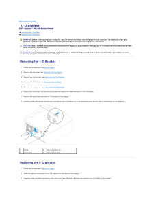
22 .Back to Contents Page I/...Back to Contents Page I/O BracketDell™ Inspiron™ 300/400 Service Manual Removing the I/O Bracket Replacing the I/O BracketWARNING: Before working inside your computer, read the safety information that shipped with your computer. For additional safety b...
-
23 .4. Using a hex nut driver...4. Using a hex nut driver, replace the two screws that secure the VGA connector to the I/O bracket.5. Replace the chassis fan (see Replacing the Chassis Fan).6. Replace the I/O bezel (see Replacing the I/O Bezel).7. Replace the top bracket (see Replacing t...
-
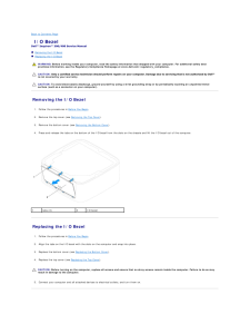
24 .Back to Contents Page I/...Back to Contents Page I/O BezelDell™ Inspiron™ 300/400 Service Manual Removing the I/O Bezel Replacing the I/O BezelWARNING: Before working inside your computer, read the safety information that shipped with your computer. For additional safety bestpra...
-
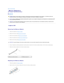
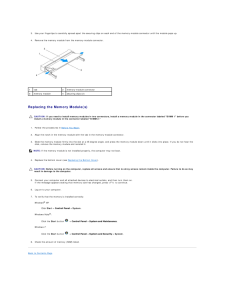
26 .Back to Contents Page Me...Back to Contents Page Memory Module(s)Dell™ Inspiron™ 300/400 Service Manual Inspiron 300 Inspiron 400WARNING: Before working inside your computer, read the safety information that shipped with your computer. For additional safety bestpractices informa...
-
27 .1cutouts (2)2tab3notch4me...1cutouts (2)2tab3notch4memory-module connector5memory module 3. Insert the memory module into the connector until the memory module snaps into position.If you insert the memory module correctly, the securing clips snap into the cutouts at each end of the ...
-
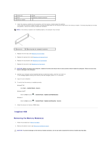
28 .3. Use your fingertips to...3. Use your fingertips to carefully spread apart the securing clips on each end of the memory-module connector until the module pops up.4. Remove the memory module from the memory-module connector.1tab2memory-module connector3memory module4securing clips (...
-
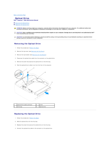
29 .Back to Contents Page Op...Back to Contents Page Optical DriveDell™ Inspiron™ 300/400 Service Manual Removing the Optical Drive Replacing the Optical DriveWARNING: Before working inside your computer, read the safety information that shipped with your computer. For additional sa...
-
30 .5. Replace the top bracke...5. Replace the top bracket (see Replacing the Top Bracket).6. Replace the top cover (see Replacing the Top Cover). CAUTION: Before turning on the computer, replace all screws and ensure that no stray screws remain inside the computer. Failure to do so mayr...
-
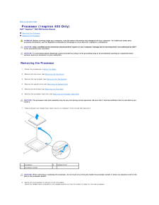
31 .Back to Contents Page Pr...Back to Contents Page Processor (Inspiron 400 Only)Dell™ Inspiron™ 300/400 Service Manual Removing the Processor Replacing the ProcessorWARNING: Before working inside your computer, read the safety information that shipped with your computer. For addit...
-
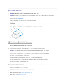
32 .Replacing the Processor ...Replacing the Processor CAUTION: Ground yourself by touching an unpainted metal surface or the computer stand. CAUTION: When replacing the processor, do not touch any of the pins inside the socket or allow any objects to fall on the pins in the socket.1. ...
-
33 .13.Replace the optical dr...13.Replace the optical drive (see Replacing the Optical Drive).14. Replace the top bracket (see Replacing the Top Bracket).15. Replace the top cover (see Replacing the Top Cover). CAUTION: Before turning on the computer, replace all screws and ensure that ...
-
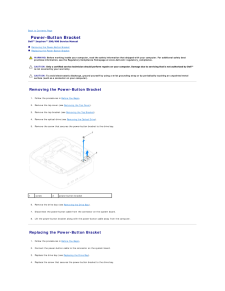
34 .Back to Contents Page Po...Back to Contents Page Power-Button BracketDell™ Inspiron™ 300/400 Service Manual Removing the Power-Button Bracket Replacing the Power-Button BracketWARNING: Before working inside your computer, read the safety information that shipped with your comput...
-
35 .5. Replace the optical dr...5. Replace the optical drive (see Replacing the Optical Drive).6. Replace the top bracket (see Replacing the Top Bracket).7. Replace the top cover (see Replacing the Top Cover). CAUTION: Before turning on the computer, replace all screws and ensure that no...
-
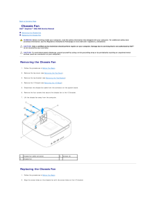
36 .Back to Contents Page Ch...Back to Contents Page Chassis FanDell™ Inspiron™ 300/400 Service Manual Removing the Chassis Fan Replacing the Chassis FanWARNING: Before working inside your computer, read the safety information that shipped with your computer. For additional safety b...
-
37 .3. Replace the four screw...3. Replace the four screws that secure the chassis fan to the I/O bracket.4. Connect the chassis fan cable to the connector on the system board.5. Replace the I/O bezel (see Replacing the I/O Bezel).6. Replace the top bracket (see Replacing the Top Bracket...
-
38 .Back to Contents Page Sy...Back to Contents Page System BoardDell™ Inspiron™ 300/400 Service Manual Removing the System Board Replacing the System Board Entering the Service Tag in the BIOSWARNING: Before working inside your computer, read the safety information that shipped wi...
-
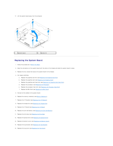
39 .17.1 Lift the system boar...17.1 Lift the system board away from the computer.system board2screws (4) Replacing the System Board1. Follow the procedures in Before You Begin.2. Align the connectors on the system board with the slots on the chassis and slide the system board in place.3...
-
40 .CAUTION: Before turning o...CAUTION: Before turning on the computer, replace all screws and ensure that no stray screws remain inside the computer. Failure to do so mayresult in damage to the computer.16. Turn on the computer.NOTE: After you have replaced the system board, enter the ...
-
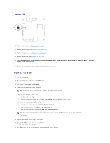
41 .Back to Contents Page Sy...Back to Contents Page System Setup UtilityDell™ Inspiron™ 300/400 Service Manual Overview Clearing Forgotten Passwords and CMOS Settings Flashing the BIOS OverviewUse system setup utility to:l Change the system configuration information after you add,...
-
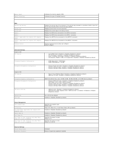
42 .Memory SpeedIndicates the...Memory SpeedIndicates the memory speed in MHzMemory TechnologyIndicates the type of installed memory MainService Tag SettingDisplays the service tag of the computer if the service tag is present or provides a field to input theservice tag manually when t...
-
43 .User PasswordStatus of us...User PasswordStatus of user password installed Boot Sequence1st Boot DeviceSpecifies the boot sequence from the available devicesHard Disk; USB; CD/DVD; Removable; Network; Disabled (Hard Disk by default)2nd Boot DeviceSpecifies the boot sequence from the ...
-
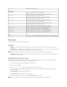
44 .Changing Boot Sequence fo...Changing Boot Sequence for Future Boots1. Enter system setup utility (see Entering System Setup Utility).2. Use the arrow keys to highlight the Boot menu option and press
to access the menu.NOTE: Write down your current boot sequence in case you wa... -
45 .Inspiron 40010. Replace t...Inspiron 40010. Replace the drive bay (see Replacing the Drive Bay).11. Replace the optical drive (see Replacing the Optical Drive).12. Replace the top bracket (see Replacing the Top Bracket).13. Replace the top cover (see Replacing the Top Cover). CAUTION...
-
46 .8.9. Click Close if the D...8.9. Click Close if the Download Complete window appears.The file icon appears on your desktop and is titled the same as the downloaded BIOS update file. Double-click the file icon on the desktop and follow the instructions on the screen.Back to Contents P...
-
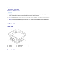
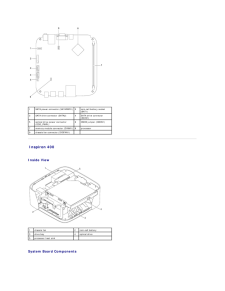
47 .Back to Contents Page Te...Back to Contents Page Technical OverviewDell™ Inspiron™ 300/400 Service Manual Inspiron™ 300 Inspiron 400WARNING: Before working inside your computer, read the safety information that shipped with your computer. For additional safety bestpractices inf...
-
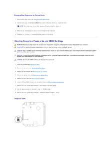
48 .1SATA power connector (SA...1SATA power connector (SATAPWR1) 2coin-cell battery socket(BAT1)3SATA drive connector (SATA2)4SATA drive connector(SATA1)5optical drive power connector(ODD_PWR1)6CMOS jumper (CMOS1)7memory-module connector (DIMM1) 8processor9chassis fan connector (SYSFAN1)...
-
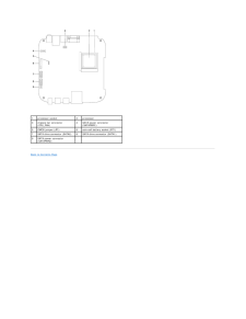
49 .1processor socket2process...1processor socket2processor3chassis fan connector(CPU_FAN)4SATA power connector(SATAPWR1)5CMOS jumper (JP1)6coin-cell battery socket (BT1)7SATA drive connector (SATA2)8SATA drive connector (SATA1)9SATA power connector(SATAPWR2) Back to Contents Page
-
50 .Back to Contents PageDell...Back to Contents PageDell™ Inspiron™ 300/400 Service Manual NOTE: A NOTE indicates important information that helps you make better use of your computer.CAUTION: A CAUTION indicates either potential damage to hardware or loss of data and tells you how to a...
-
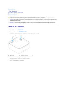
51 .Back to Contents Page To...Back to Contents Page Top BracketDell™ Inspiron™ 300/400 Service Manual Removing the Top Bracket Replacing the Top BracketWARNING: Before working inside your computer, read the safety information that shipped with your computer. For additional safety b...
-
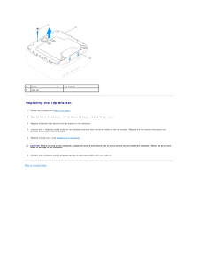
52 .1screw2top bracket3tabs (...1screw2top bracket3tabs (2) Replacing the Top Bracket1. Follow the procedures in Before You Begin.2. Align the tabs on the top bracket with the slots on the chassis and place the top bracket.3. Replace the screw that secures the top bracket to the comput...
-
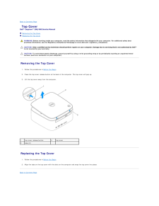
53 .Back to Contents Page To...Back to Contents Page Top CoverDell™ Inspiron™ 300/400 Service Manual Removing the Top Cover Replacing the Top CoverWARNING: Before working inside your computer, read the safety information that shipped with your computer. For additional safety bestpra...
