
ThinkPad R61の取扱説明書・マニュアル [全256ページ 6.43MB]


2


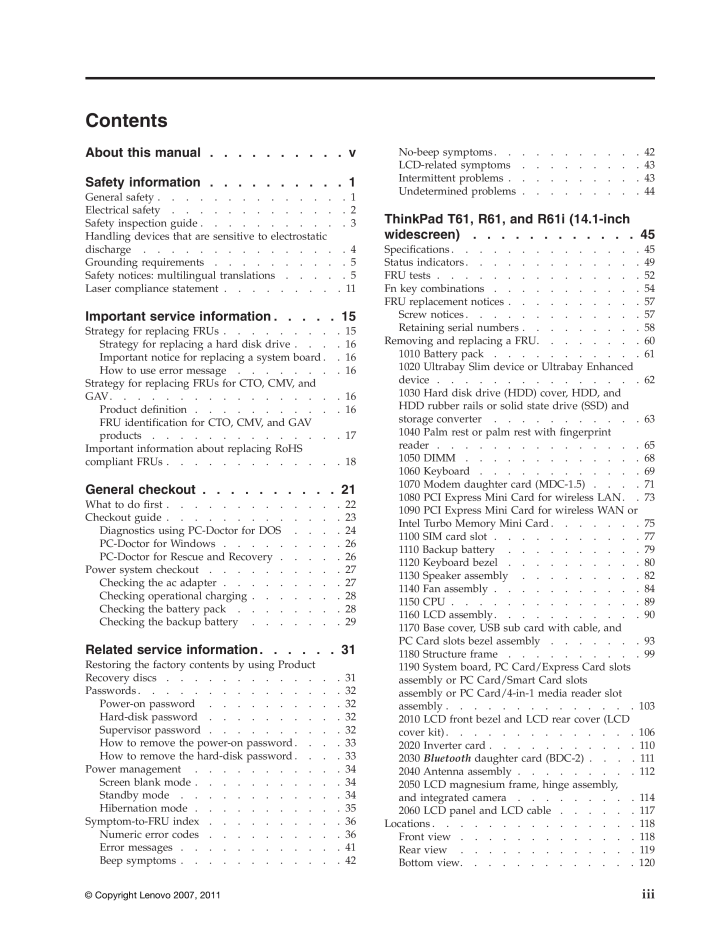

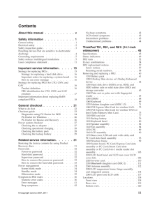


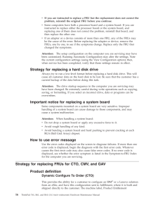
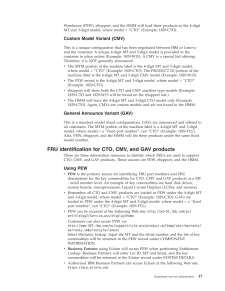
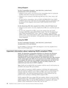

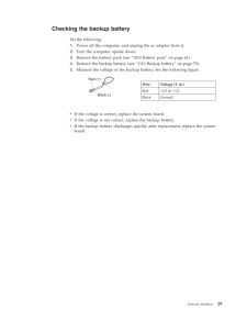

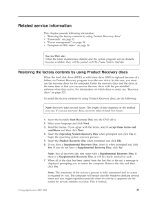
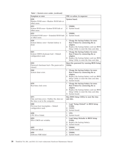
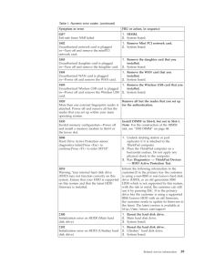
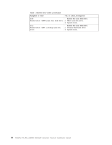
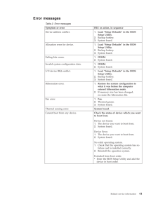
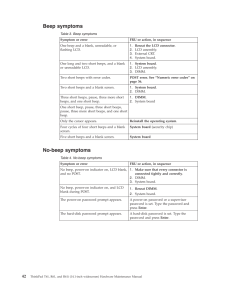
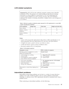
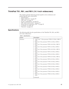
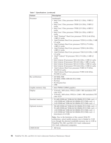
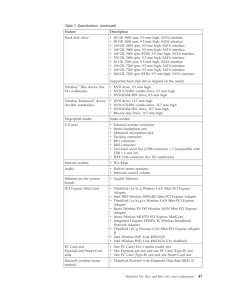
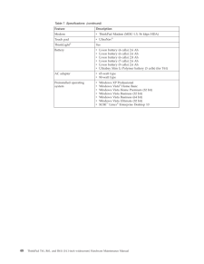
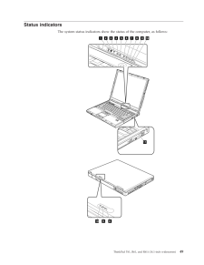
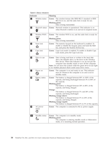
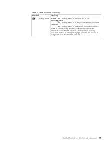
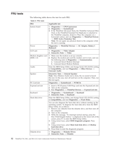
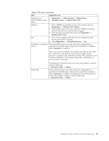
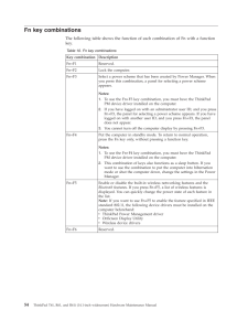
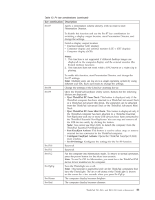
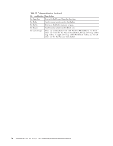
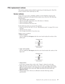
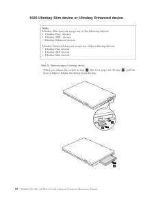
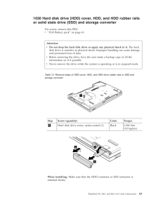
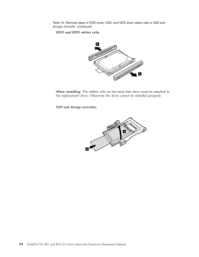
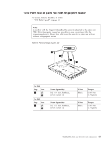
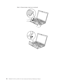
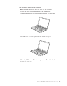
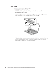
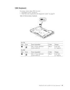
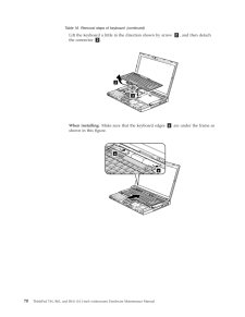
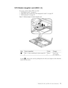
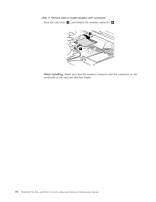
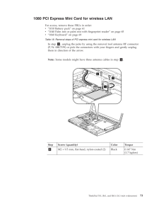
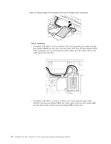
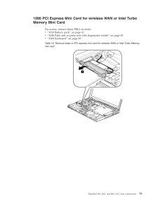
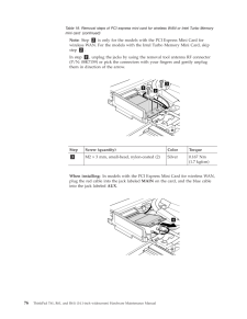
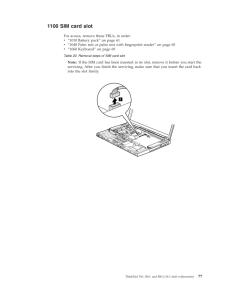
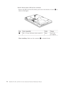
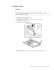
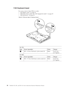
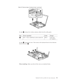
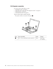
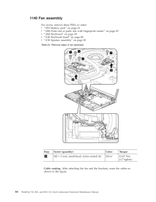
Contents About this manual . . . . . . . . . .v Safety information . . . . . . . . . .1 General safety . . . . . . . . . . . . . .1 Electrical safety . . . . . . . . . . . . .2 Safety inspection guide . . . . . . . . . . .3 Handling devices that are sensitive to electrostatic discharge . . . . . . . . . . . . . . .4 Grounding requirements . . . . . . . . . .5 Safety notices: multilingual translations . . . . .5 Laser compliance statement . . . . . . . . .11 Important service information . . . . .15 Strategy for replacing FRUs . . . . . . . . .15 Strategy for replacing a hard disk drive . . . .16 Important notice for replacing a system board . .16 How to use error message . . . . . . . .16 Strategy for replacing FRUs for CTO, CMV, and GAV . . . . . . . . . . . . . . . . .16 Product definition . . . . . . . . . . .16 FRU identification for CTO, CMV, and GAV products . . . . . . . . . . . . . .17 Important information about replacing RoHS compliant FRUs . . . . . . . . . . . . .18 General checkout . . . . . . . . . .21 What to do first . . . . . . . . . . . . .22 Checkout guide . . . . . . . . . . . . .23 Diagnostics using PC-Doctor for DOS . . . .24 PC-Doctor for Windows . . . . . . . . .26 PC-Doctor for Rescue and Recovery . . . . .26 Power system checkout . . . . . . . . . .27 Checking the ac adapter . . . . . . . . .27 Checking operational charging . . . . . . .28 Checking the battery pack . . . . . . . .28 Checking the backup battery . . . . . . .29 Related service information . . . . . .31 Restoring the factory contents by using Product Recovery discs . . . . . . . . . . . . .31 Passwords . . . . . . . . . . . . . . .32 Power-on password . . . . . . . . . .32 Hard-disk password . . . . . . . . . .32 Supervisor password . . . . . . . . . .32 How to remove the power-on password . . . .33 How to remove the hard-disk password . . . .33 Power management . . . . . . . . . . .34 Screen blank mode . . . . . . . . . . .34 Standby mode . . . . . . . . . . . .34 Hibernation mode . . . . . . . . . . .35 Symptom-to-FRU index . . . . . . . . . .36 Numeric error codes . . . . . . . . . .36 Error messages . . . . . . . . . . . .41 Beep symptoms . . . . . . . . . . . .42 No-beep symptoms . . . . . . . . . . .42 LCD-related symptoms . . . . . . . . .43 Intermittent problems . . . . . . . . . .43 Undetermined problems . . . . . . . . .44 ThinkPad T61, R61, and R61i (14.1-inch widescreen) . . . . . . . . . . . .45 Specifications . . . . . . . . . . . . . .45 Status indicators . . . . . . . . . . . . .49 FRU tests . . . . . . . . . . . . . . .52 Fn key combinations . . . . . . . . . . .54 FRU replacement notices . . . . . . . . . .57 Screw notices . . . . . . . . . . . . .57 Retaining serial numbers . . . . . . . . .58 Removing and replacing a FRU . . . . . . . .60 1010 Battery pack . . . . . . . . . . .61 1020 Ultrabay Slim device or Ultrabay Enhanced device . . . . . . . . . . . . . . .62 1030 Hard disk drive (HDD) cover, HDD, and HDD rubber rails or solid state drive (SSD) and storage converter . . . . . . . . . . .63 1040 Palm rest or palm rest with fingerprint reader . . . . . . . . . . . . . . .65 1050 DIMM . . . . . . . . . . . . .68 1060 Keyboard . . . . . . . . . . . .69 1070 Modem daughter card (MDC-1.5) . . . .71 1080 PCI Express Mini Card for wireless LAN . .73 1090 PCI Express Mini Card for wireless WAN or Intel Turbo Memory Mini Card . . . . . . .75 1100 SIM card slot . . . . . . . . . . .77 1110 Backup battery . . . . . . . . . .79 1120 Keyboard bezel . . . . . . . . . .80 1130 Speaker assembly . . . . . . . . .82 1140 Fan assembly . . . . . . . . . . .84 1150 CPU . . . . . . . . . . . . . .89 1160 LCD assembly . . . . . . . . . . .90 1170 Base cover, USB sub card with cable, and PC Card slots bezel assembly . . . . . . .93 1180 Structure frame . . . . . . . . . .99 1190 System board, PC Card/Express Card slots assembly or PC Card/Smart Card slots assembly or PC Card/4-in-1 media reader slot assembly . . . . . . . . . . . . . . 103 2010 LCD front bezel and LCD rear cover (LCD cover kit) . . . . . . . . . . . . . . 106 2020 Inverter card . . . . . . . . . . .110 2030 Bluetooth daughter card (BDC-2) . . . . 111 2040 Antenna assembly . . . . . . . . .112 2050 LCD magnesium frame, hinge assembly, and integrated camera . . . . . . . . .114 2060 LCD panel and LCD cable . . . . . .117 Locations . . . . . . . . . . . . . . .118 Front view . . . . . . . . . . . . .118 Rear view . . . . . . . . . . . . .119 Bottom view . . . . . . . . . . . . . 120 iii© Copyright Lenovo 2007, 2011


