
OptiPlex 160Lの取扱説明書・マニュアル [全16ページ 0.56MB]


2


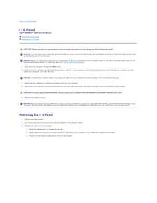
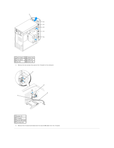
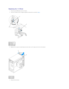

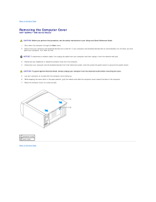
Back to Contents Page I/O PanelDell™ OptiPlex™ 160L Service Manual Removing the I/O Panel Replacing the I/O PanelCAUTION: Before you perform this procedure, see the safety instructions in your Setup and Quick Reference Guide. NOTICE: To avoid electrostatic discharge, ground yourself by using a wrist grounding strap or by periodically touching an unpainted metal surface (suchas the back panel) on the computer. NOTICE: Before you disconnect a device from the computer or remove a component from the system board, verify that the standby power light on thesystem board has turned off. To locate the light, see "System Board Components."1. Shut down the computer through the Start menu.2. Ensure that your computer and attached devices are turned off. If your computer and attached devices did not automatically turn off when you shutdown your computer, turn them off now. NOTICE: To disconnect a network cable, first unplug the cable from your computer and then unplug it from the network wall jack.3. Disconnect any telephone or telecommunication lines from the computer.4. Disconnect your computer and all attached devices from their electrical outlets, and press the power button to ground the system board. CAUTION: To guard against electrical shock, always unplug your computer from the electrical outlet before removing the cover.5. Remove the computer cover. NOTICE: Before touching anything inside your computer, ground yourself by touching an unpainted metal surface, such as the metal at the back of thecomputer. While you work, periodically touch an unpainted metal surface to dissipate any static electricity that could harm internal components. Removing the I/O Panel1. Remove the hard drive(s).2. Cut the tie wrap cord that secures the I/O panel cables to the computer frame.3. Release and remove the front panel:a. Reach inside the computer and push the bottom tab toward you to release it (the middle tab releases automatically).c. Push the release lever to release the top tab.b. Rotate the front panel to separate it from the side hinges.


