
ThinkPad R500の取扱説明書・マニュアル [全226ページ 6.93MB]


0


122 / 226 ページ
122 / 226 ページ


現在のページURL
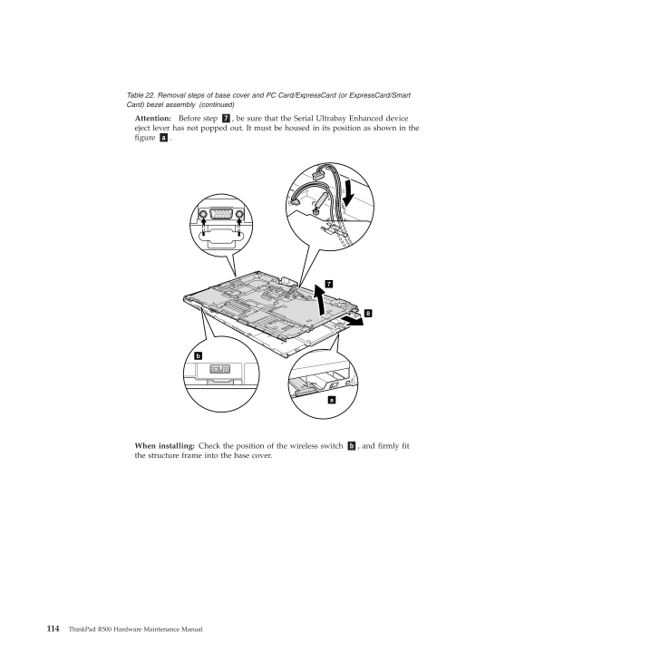
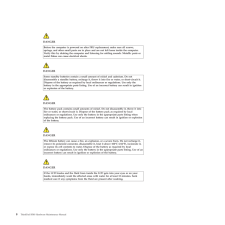
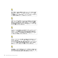
Table 22. Removal steps of base cover and PC Card/ExpressCard (or ExpressCard/SmartCard) bezel assembly (continued)Attention:Before step7, be sure that the Serial Ultrabay Enhanced deviceeject lever has not popped out. It must be housed in its position as shown in thefigurea.a78bWhen installing:Check the position of the wireless switch b, and firmly fitthe structure frame into the base cover.114 ThinkPad R500 Hardware Maintenance Manual
参考になったと評価  34人が参考になったと評価しています。
その他の取扱説明書

3920 view

2583 view

477 view

1202 view

80 view
このマニュアルの目次
-
2 .2 ページ目のマニュアル
-
4 .NoteBefore using this inf...NoteBefore using this information and the product it supports, be sure to read the general information under "Notices" on page215.Third Edition (September 2009)(C) Copyright Lenovo 2008, 2009.LENOVO products, data, computer software, and services have been...
-
5 .ContentsAbout this manual...ContentsAbout this manual..........vSafety information..........1General safety..............2Electrical safety.............3Safety inspection guide ...........5Handling devices that are sensitive to electrostaticdischarge...............6Grounding requirem...
-
6 .Parts list.............14...Parts list.............141Overall...............142LCD FRUs..............179Keyboard...............190Miscellaneous parts ...........192AC adapters..............194Power cords..............195Recovery discs.............196Windows XP Professional (32 bit) D...
-
7 .About this manualThis man...About this manualThis manual contains service and reference information for the followingThinkPad(R)products.ThinkPad R500MT 2713, 2714, 2716, 2717, 2718, 2719, 2720, 2731, 2732, 2733, 2734, 2735,2736, and 2737Use this manual along with the advanced diagno...
-
9 .Safety informationThis ch...Safety informationThis chapter presents following safety information that you need to be familiarwith before you service a ThinkPad Notebook.v"General safety" on page 2v"Electrical safety" on page 3v"Safety inspection guide" on page 5v"Handling devices tha...
-
10 .General safetyFollow thes...General safetyFollow these rules to ensure general safety:vObserve good housekeeping in the area of the machines during and aftermaintenance.vWhen lifting any heavy object:1.Make sure that you can stand safely without slipping.2.Distribute the weight of th...
-
11 .Electrical safetyObserve ...Electrical safetyObserve the following rules when working on electrical equipment.vFind the room emergency power-off (EPO) switch, disconnecting switch, orelectrical outlet. If an electrical accident occurs, you can then operate the switchor unplug the pow...
-
12 .vDo not touch live electr...vDo not touch live electrical circuits with the reflective surface of a plastic dentalmirror. The surface is conductive; such touching can cause personal injury andmachine damage.vDo not service the following parts with the power onwhen they are removedfro...
-
13 .Safety inspection guideTh...Safety inspection guideThe purpose of this inspection guide is to assist you in identifying potentiallyunsafe conditions. As each machine was designed and built, required safety itemswere installed to protect users and service technicians from injury. This...
-
14 .Handling devices that are...Handling devices that are sensitive to electrostatic dischargeAny computer part containing transistors or integrated circuits (ICs) should beconsidered sensitive to electrostatic discharge (ESD.) ESD damage can occur whenthere is a difference in charge bet...
-
15 .Safety notices (multiling...Safety notices (multilingual translations)The safety notices in this section are provided in the following languages:vEnglishvArabicvBrazilian PortuguesevFrenchvGermanvHebrewvJapanesevKoreanvSpanishvTraditional ChineseSafety information 7
-
16 .DANGERBefore the computer...DANGERBefore the computer is powered on after FRU replacement, make sure all screws,springs, and other small parts are in place and are not left loose inside the computer.Verify this by shaking the computer and listening for rattling sounds. Metallic parts...
-
17 .DANGERTo avoid shock, do ...DANGERTo avoid shock, do not remove the plastic cover that protects the lower part of theinverter card.DANGERThough the main batteries have low voltage, a shorted or grounded battery can produceenough current to burn personnel or combustible materials.DANG...
-
20 .PERIGOAntes de ligar o co...PERIGOAntes de ligar o computador apos a substituicao da FRU, certifique-se de que todos osparafusos, molas e outras pecas pequenas estejam no lugar e nao estejam soltos dentrodo computador. Verifique isso sacudindo o computador e procurando ouvir sons dep...
-
21 .PERIGOPara evitar choque ...PERIGOPara evitar choque eletrico, nao remova a capa plastica que protege a parte inferior daplaca inversora.PERIGOEmbora as principais baterias possuam baixa voltagem, uma bateria em curto-circuito ouaterrada pode produzir corrente o bastante para queimar...
-
22 .DANGERAvant de remettre l...DANGERAvant de remettre l'ordinateur sous tension apres remplacement d'une unite en clientele,verifiez que tous les ressorts, vis et autres pieces sont bien en place et bien fixees. Pource faire, secouez l'unite et assurez-vous qu'aucun bruit suspect ne se...
-
23 .DANGERAfin d'eviter tout ...DANGERAfin d'eviter tout risque de choc electrique, ne retirez pas le cache en plastiqueprotegeant la partie inferieure de la carte d'alimentation.DANGERBien que le voltage des batteries principales soit peu eleve, le court-circuit ou la mise ala masse d'u...
-
24 .VORSICHTBevor nach einem ...VORSICHTBevor nach einem FRU-Austausch der Computer wieder angeschlossen wird,mu sichergestellt werden, da keine Schrauben, Federn oder andere Kleinteilefehlen oder im Gehause vergessen wurden. Der Computer mu geschuttelt undauf Klappergerausche gepruft we...
-
25 .VORSICHTDie Leuchtstoffro...VORSICHTDie Leuchtstoffrohre im LCD-Bildschirm enthalt Quecksilber. Bei derEntsorgung die ortlichen Bestimmungen fur Sondermull beachten. DerLCD-Bildschirm besteht aus Glas und kann zerbrechen, wenn er unsachgemabehandelt wird oder der Computer auf den Bod...
-
32 .PELIGROAntes de encender ...PELIGROAntes de encender el sistema despues de sustituir una FRU, compruebe que todos lostornillos, muelles y demas piezas pequenas se encuentran en su sitio y no se encuentransueltas dentro del sistema. Compruebelo agitando el sistema y escuchando los pos...
-
33 .PELIGROPara evitar descar...PELIGROPara evitar descargas, no quite la cubierta de plastico que rodea la parte baja de latarjeta invertida.PELIGROAunque las baterias principales tienen un voltaje bajo, una bateria cortocircuitada o concontacto a tierra puede producir la corriente sufi...
-
36 .Laser compliance statemen...Laser compliance statement (multilingual translations)The laser compliance statements in this section are provided in the followinglanguages:vEnglishvArabicvBrazilian PortuguesevFrenchvGermanvHebrewvJapanesevKoreanvSpanishvTraditional ChineseSome models of...
-
38 .Alguns modelos de computa...Alguns modelos de computador ThinkPad sao equipados na fabrica com umdispositivo de armazenamento otico, como uma unidade de CD-ROM ou deDVD-ROM. Tais dispositivos tambem sao vendidos separadamente comoopcionais. Se uma dessas unidades estiver instalada, e...
-
39 .Certains modeles d'ordina...Certains modeles d'ordinateur ThinkPad sont equipes d'origine d'une unite destockage optique telle qu'une unite de CD-ROM ou de DVD-ROM. Ces unites sontegalement vendues separement en tant qu'options. Si l'une de ces unites estinstallee, elle est certifiee...
-
40 .Einige ThinkPad-Modelle s...Einige ThinkPad-Modelle sind werkseitig mit einem CD-ROM- oderDVD-ROM-Laufwerk ausgestattet. CD- und DVD-Laufwerke konnen auchgesondert als Zusatzeinrichtung erworben werden. Die Laufwerke erfullen dieAnforderungen gema IEC 60825-1 (International Electrote...
-
44 .Algunos modelos de sistem...Algunos modelos de sistemas ThinkPad estan equipados de fabrica con undispositivo de almacenamiento optico, como una unidad de CD-ROM o deDVD-ROM. Estas unidades tambien se venden por separado como opciones. Siesta instalada alguna de dichas unidades, se c...
-
47 .Important service informa...Important service informationThis chapter presents following important service information that applies to allmachine types supported by this manual:v"Strategy for replacing FRUs"- "Strategy for replacing a hard disk drive" on page 40- "Important notice fo...
-
48 .Use the following strateg...Use the following strategy to prevent unnecessary expense for replacing andservicing FRUs:vIf you are instructed to replace a FRU but the replacement does not correct theproblem, reinstall the original FRU before you continue .vSome computers have both a p...
-
49 .Strategy for replacing FR...Strategy for replacing FRUs for CTO, CMV, and GAVProduct definitionDynamic Configure To Order (CTO)This provides the ability for a customer to configure an IBM(R)or a Lenovo solutionfrom an eSite, and have this configuration sent to fulfillment, where it i...
-
50 .vBusiness Partnersusing E...vBusiness Partnersusing Eclaim will access PEW when performing EntitlementLookup. Business Partners will enter Loc ID, MT and Serial, and the keycommodities will be returned in the Eclaim record under SYSTEM DETAILS.vAuthorized IBM Business Partners can ac...
-
51 .General checkoutThis chap...General checkoutThis chapter presents following information:v"What to do first" on page 44v"Checkout guide" on page 45- "Diagnostics using PC-Doctor for DOS" on page 45- "Lenovo ThinkVantage Toolbox (Lenovo System Toolbox)" on page 48- "PC-Doctor for Windo...
-
52 .What to do firstWhen you ...What to do firstWhen you do return a FRU, you must include the following information in theparts exchange form or parts return form that you attach to it:__ 1.Name and phone number of service technician__ 2.Date of service__ 3.Date on which the machine fai...
-
53 .Checkout guideUse the fol...Checkout guideUse the following procedures as a guide in identifying and correcting problemswith the ThinkPad Notebook.Note:The diagnostic tests are intended to test only ThinkPad products. The use ofnon-ThinkPad products, prototype cards, or modified opti...
-
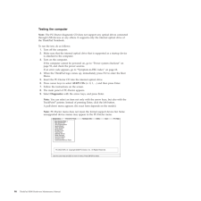
54 .Testing the computerNote:...Testing the computerNote:The PC-Doctor diagnostic CD does not support any optical drives connectedthrough USB devices or any others. It supports only the internal optical drive ofthe ThinkPad Notebook.To run the test, do as follows:1.Turn off the computer....
-
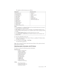
55 .The options on the test m...The options on the test menu are as follows:Diagnostics Interactive TestsvRun Normal TestvRun Quick TestvCPU/CoprocessorvSystemboardvVideo AdaptervSerial PortsvParallel PortsvFixed DisksvDiskette DrivesvOther DevicesvThinkPad DevicesvCommunicationvWireless...
-
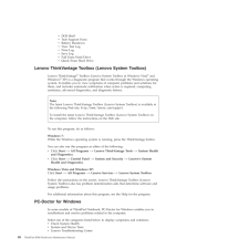
56 .vDOS ShellvTech Support F...vDOS ShellvTech Support FormvBattery RundownvView Test LogvPrint LogvSave LogvFull Erase Hard DrivevQuick Erase Hard DriveLenovo ThinkVantage Toolbox (Lenovo System Toolbox)Lenovo ThinkVantage(R)Toolbox (Lenovo System Toolbox in Windows Vista(R)andWindows(...
-
57 .vSystem ReportsvUpdates a...vSystem ReportsvUpdates and SupportPC-Doctor for Rescue and RecoveryIn some models of ThinkPad Notebook, the Rescue and Recovery(R)workspaceenables you to run the PC-Doctor program to test the hardware features of thecomputer.To run the test, click "Run Di...
-
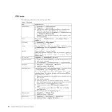
58 .FRU testsThe following ta...FRU testsThe following table shows the test for each FRU.Table 1. FRU testsFRU Applicable testSystem board 1.Diagnostics-->CPU/Coprocessor2.Diagnostics-->Systemboard3.If the docking station or the port replicator is attached to theThinkPad computer, detach...
-
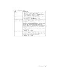
59 .Table 1. FRU tests (conti...Table 1. FRU tests (continued)FRU Applicable testMemory 1.If two DIMMs are installed, remove one of them and runDiagnostics-->Advanced Memory Tests .2.If the problem does not recur, return the DIMM to its place,remove the other one, and run the test again....
-
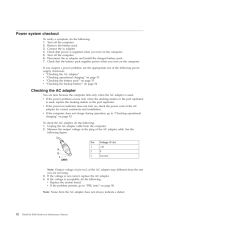
60 .Power system checkoutTo v...Power system checkoutTo verify a symptom, do the following:1.Turn off the computer.2.Remove the battery pack.3.Connect the ac adapter.4.Check that power is supplied when you turn on the computer.5.Turn off the computer.6.Disconnect the ac adapter and insta...
-
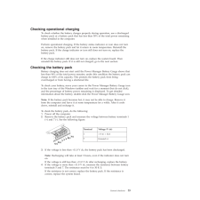
61 .Checking operational char...Checking operational chargingTo check whether the battery charges properly during operation, use a dischargedbattery pack or a battery pack that has less than 50% of the total power remainingwhen installed in the computer.Perform operational charging. If t...
-
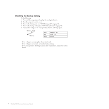
62 .Checking the backup batte...Checking the backup batteryDo the following:1.Power off the computer, and unplug the ac adapter from it.2.Turn the computer upside down.3.Remove the battery pack (see "1010 Battery pack" on page 84).4.Remove the backup battery (see "1090 Backup battery" on...
-
63 .Related service informati...Related service informationThis chapter presents following information:v"Restoring the factory contents by using Product Recovery discs"v"Restoring the factory contents by using Recovery Disc Set" on page 56v"Passwords" on page 57v"Power management" on pag...
-
64 .8.When the recovery proce...8.When the recovery process is complete, the Welcome to Microsoft Windowsscreen is displayed. Follow the instructions on the screen to complete theWindows setup.Restoring the factory contents by using Recovery Disc SetWhen the hard disk drive is replaced b...
-
65 .5.Read the license. If yo...5.Read the license. If you agree with the terms and conditions, select I acceptthese terms and conditions and then clickNext. If you do not agree with theterms and conditions, follow the instructions on the screen.6.ClickYes in the displayed window to begi...
-
66 .Note:There are two modes ...Note:There are two modes for the HDP: User onlyandMaster + User. TheMaster + Usermode requires two HDPs; the system administrator enters both inthe same operation. The system administrator then provides the user HDP to thesystem user.Attention:If the user ...
-
67 .5.SelectPower-On Password...5.SelectPower-On Password.6.Type the current SVP in the Enter Current Password field. then leave theEnterNew Passwordfield blank, and press Enter twice.7.In the Changes have been saved window, press Enter.8.Press F10; then, in the Setup confirmation window...
-
68 .Power managementTo reduce...Power managementTo reduce power consumption, the computer has three power management modes:screen blank, sleep (standby in Windows XP), and hibernation.Screen blank modeIf the time set on the "Turn off monitor" timer in the operating system expires, theLCD...
-
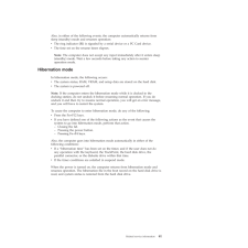
69 .Also, in either of the fo...Also, in either of the following events, the computer automatically returns fromsleep (standby) mode and resumes operation:vThe ring indicator (RI) is signaled by a serial device or a PC Card device.vThe time set on the resume timer elapses.Note:The comput...
-
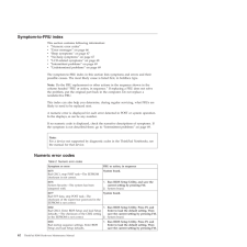
70 .Symptom-to-FRU indexThis ...Symptom-to-FRU indexThis section contains following information:v"Numeric error codes"v"Error messages" on page 66v"Beep symptoms" on page 67v"No-beep symptoms" on page 67v"LCD-related symptoms" on page 68v"Intermittent problems" on page 69v"Undetermined p...
-
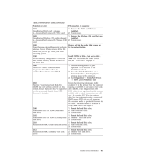
71 .Table 2. Numeric error co...Table 2. Numeric error codes (continued)Symptom or error FRU or action, in sequence0187EAIA data access error-The access toEEPROM is failed.System board.0188Invalid RFID Serialization Information Area.System board.0189Invalid RFID configuration information...
-
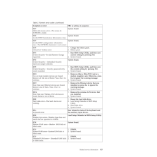
72 .Table 2. Numeric error co...Table 2. Numeric error codes (continued)Symptom or error FRU or action, in sequence0250System battery error-System battery isdead.1.Charge the backup battery for morethan 8 hours by connecting the acadapter.2.Replace the backup battery and run BIOSSetup Ut...
-
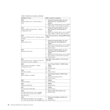
73 .Table 2. Numeric error co...Table 2. Numeric error codes (continued)Symptom or error FRU or action, in sequence1804Unauthorized WAN card is pluggedin-Power off and remove the WAN card.1.Remove the WAN card that youinstalled.2.System board.1805Unauthorized Wireless USB card is plugged...
-
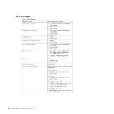
74 .Error messagesTable 3. Er...Error messagesTable 3. Error messagesSymptom or error FRU or action, in sequenceDevice address conflict. 1.Load "Setup Defaults" in the BIOSSetup Utility.2.Backup battery.3.System board.Allocation error for device. 1.Load "Setup Defaults" in the BIOSSetup ...
-
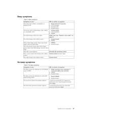
75 .Beep symptomsTable 4. Bee...Beep symptomsTable 4. Beep symptomsSymptom or error FRU or action, in sequenceOne beep and a blank, unreadable, orflashing LCD.1.Reseat the LCD connector .2.LCD assembly.3.External CRT.4.System board.One long and two short beeps, and a blankor unreadable L...
-
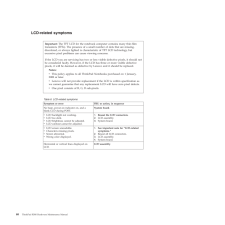
76 .LCD-related symptomsTable...LCD-related symptomsTable 6. LCD-related symptomsSymptom or error FRU or action, in sequenceNo beep, power-on indicator on, and ablank LCD during POST.System board.vLCD backlight not working.vLCD too dark.vLCD brightness cannot be adjusted.vLCD contrast ca...
-
77 .Intermittent problemsInte...Intermittent problemsIntermittent system hang problems can be due to a variety of causes that havenothing to do with a hardware defect, such as cosmic radiation, electrostaticdischarge, or software errors. FRU replacement should be considered only when apr...
-
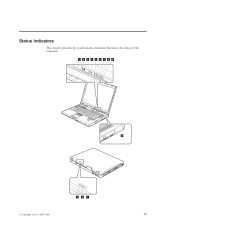
79 .Status indicatorsThis cha...Status indicatorsThis chapter presents the system status indicators that show the status of thecomputer.101 2 3 4 5 6 7 8 97 8 9(C) Copyright Lenovo 2008, 2009 71
-
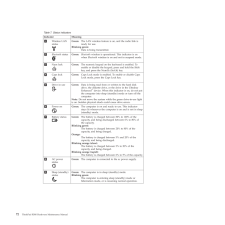
80 .Table 7. Status indicator...Table 7. Status indicatorsIndicator Meaning1Wireless LANstatusGreen:The LAN wireless feature is on, and the radio link isready for use.Blinking green:Data is being transmitted.2BluetoothstatusRGreen:Bluetoothwireless is operational. This indicator is onwhe...
-
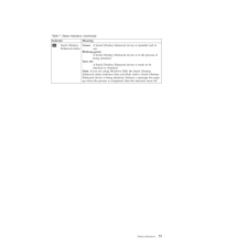
81 .Table 7. Status indicator...Table 7. Status indicators (continued)Indicator Meaning10Serial UltrabayEnhanced statusGreen:A Serial Ultrabay Enhanced device is installed and inuse.Blinking green:A Serial Ultrabay Enhanced device is in the process ofbeing detached.Turn off:A Serial Ultr...
-
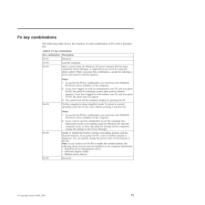
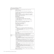
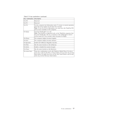
83 .Fn key combinationsThe fo...Fn key combinationsThe following table shows the function of each combination of Fn with a functionkey.Table 8. Fn key combinationsKey combination DescriptionFn+F1 Reserved.Fn+F2 Lock the computer.Fn+F3 Select a power plan (in Windows XP, power scheme) tha...
-
84 .Table 8. Fn key combinati...Table 8. Fn key combinations (continued)Key combination DescriptionFn+F7 Apply a presentation scheme directly, with no need to startPresentation Director.To disable this function and use the Fn+F7 key combination forswitching a display output location, sta...
-
85 .Table 8. Fn key combinati...Table 8. Fn key combinations (continued)Key combination DescriptionFn+F10 Reserved.Fn+F11 Reserved.Fn+F12 Put the computer into hibernation mode. To return to normal operation,press the power button for less than four seconds.Note:To use Fn+F12 for hiberna...
-
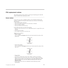
87 .FRU replacement noticesTh...FRU replacement noticesThis chapter presents notices related to removing and replacing parts. Read thischapter carefully before replacing any FRU.Screw noticesLoose screws can cause a reliability problem. In the ThinkPad Notebook, thisproblem is addressed ...
-
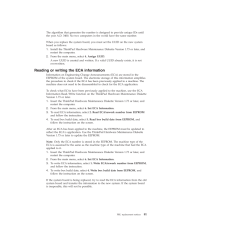
88 .Retaining serial numbersT...Retaining serial numbersThis section includes the following descriptions:v"Restoring the serial number of the system unit"v"Retaining the UUID"v"Reading or writing the ECA information" on page 81Restoring the serial number of the system unitWhen the comput...
-
89 .The algorithm that genera...The algorithm that generates the number is designed to provide unique IDs untilthe year A.D. 3400. No two computers in the world have the same number.When you replace the system board, you must set the UUID on the new systemboard as follows:1.Install the T...
-
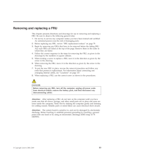
91 .Removing and replacing a ...Removing and replacing a FRUThis chapter presents directions and drawings for use in removing and replacing aFRU. Be sure to observe the following general rules:1.Do not try to service any computer unless you have been trained and certified.An untrained pe...
-
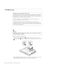
92 .1010 Battery packDANGERUs...1010 Battery packDANGERUse only the battery specified in the parts list for your computer. Any otherbattery could ignite or explode.Table 9. Removal steps of battery packUnlock the battery release lever 1. Holding the battery release lever in theunlocked p...
-
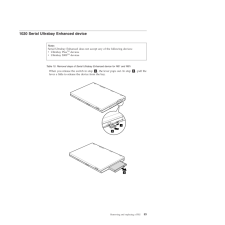
93 .1020 Serial Ultrabay Enha...1020 Serial Ultrabay Enhanced deviceTable 10. Removal steps of Serial Ultrabay Enhanced device for R61 and R61iWhen you release the switch in step 1, the lever pops out. In step 2, pull thelever a little to release the device from the bay.123Note:Serial Ul...
-
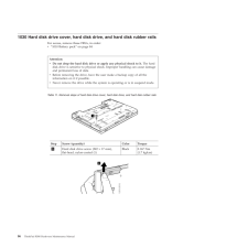
94 .1030 Hard disk drive cove...1030 Hard disk drive cover, hard disk drive, and hard disk rubber railsFor access, remove these FRUs, in order:v"1010 Battery pack" on page 84Table 11. Removal steps of hard disk drive cover, hard disk drive, and hard disk rubber rails1Step Screw (quantity...
-
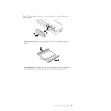
95 .Table 11. Removal steps o...Table 11. Removal steps of hard disk drive cover, hard disk drive, and hard disk rubberrails (continued)345When installing:Make sure that the hard disk drive connector is attachedfirmly.66When installing:The rubber rails on the hard disk drive must be atta...
-
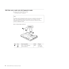
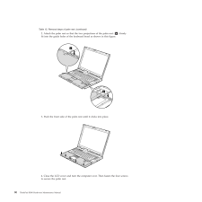
96 .1040 Palm rest or palm re...1040 Palm rest or palm rest with fingerprint readerFor access, remove these FRUs, in order:v"1010 Battery pack" on page 84Table 12. Removal steps of palm rest1111Step Icon Screw (quantity) Color Torque1M2× 17 mm, flat-head,nylon-coated (4)Black 0.167 Nm(1....
-
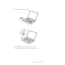
97 .Table 12. Removal steps o...Table 12. Removal steps of palm rest (continued)223When installing:When you attach the palm rest, do as follows:1. Attach the fingerprint reader connector firmly to the system board.Removing and replacing a FRU 89
-
98 .Table 12. Removal steps o...Table 12. Removal steps of palm rest (continued)2. Attach the palm rest so that the two projections of the palm rest ( a) firmlyfit into the guide holes of the keyboard bezel as shown in this figure.aa3. Push the front side of the palm rest until it clicks...
-
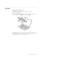
99 .1050 DIMMFor access, remo...1050 DIMMFor access, remove these FRUs, in order:v"1010 Battery pack" on page 84v"1040 Palm rest or palm rest with fingerprint reader" on page 88Table 13. Removal steps of dimmNote:If only one DIMM is used on the computer you are servicing, the cardmust be...
-
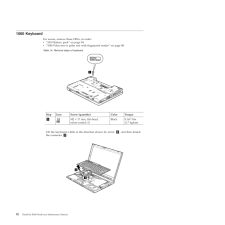
100 .1060 KeyboardFor access, ...1060 KeyboardFor access, remove these FRUs, in order:v"1010 Battery pack" on page 84v"1040 Palm rest or palm rest with fingerprint reader" on page 88Table 14. Removal steps of keyboard1Step Icon Screw (quantity) Color Torque1M2× 17 mm, flat-head,nylon-coat...
