
OptiPlex G1の取扱説明書・マニュアル [全174ページ 1.59MB]


2


118 / 174 ページ
118 / 174 ページ


現在のページURL
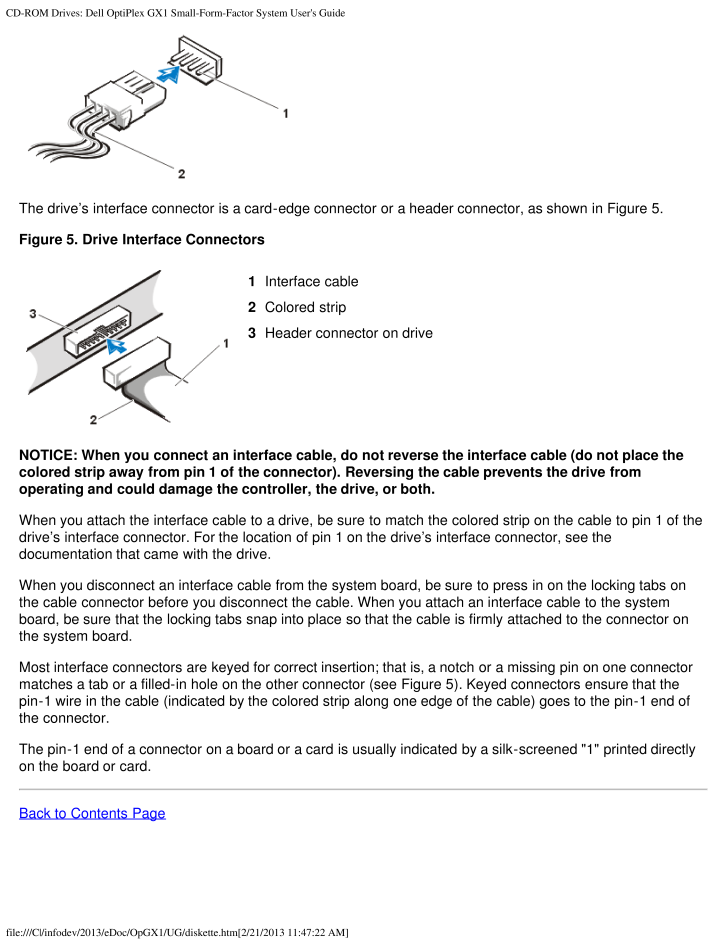
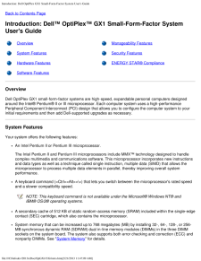
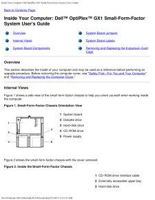
CD-ROM Drives: Dell OptiPlex GX1 Small-Form-Factor System User's Guidefile:///C|/infodev/2013/eDoc/OpGX1/UG/diskette.htm [2/21/2013 11:47:22 AM]The drive's interface connector is a card-edge connector or a header connector, as shown in Figure 5.Figure 5. Drive Interface Connectors1Interface cable2Colored strip3Header connector on driveNOTICE: When you connect an interface cable, do not reverse the interface cable (do not place thecolored strip away from pin 1 of the connector). Reversing the cable prevents the drive fromoperating and could damage the controller, the drive, or both.When you attach the interface cable to a drive, be sure to match the colored strip on the cable to pin 1 of thedrive's interface connector. For the location of pin 1 on the drive's interface connector, see thedocumentation that came with the drive.When you disconnect an interface cable from the system board, be sure to press in on the locking tabs onthe cable connector before you disconnect the cable. When you attach an interface cable to the systemboard, be sure that the locking tabs snap into place so that the cable is firmly attached to the connector onthe system board.Most interface connectors are keyed for correct insertion; that is, a notch or a missing pin on one connectormatches a tab or a filled-in hole on the other connector (see Figure 5 ). Keyed connectors ensure that thepin-1 wire in the cable (indicated by the colored strip along one edge of the cable) goes to the pin-1 end ofthe connector.The pin-1 end of a connector on a board or a card is usually indicated by a silk-screened "1" printed directlyon the board or card.Back to Contents Page
参考になったと評価  2人が参考になったと評価しています。
その他の取扱説明書

296 view

216 view

284 view
このマニュアルの目次
-
1 .Contents: Dell OptiPlex G...Contents: Dell OptiPlex GX1 Small-Form-Factor System User's Guidefile:///C|/infodev/2013/eDoc/OpGX1/UG/index.htm [2/21/2013 11:47:08 AM]DellTM OptiPlexTM GX1 Small-Form-Factor System User's GuideIntroductionSetup and OperationUsing the System Setup Program...
-
2 .2 ページ目のマニュアルContents: Dell OptiPlex GX1 Small-Form-Factor System User's Guidefile:///C|/infodev/2013/eDoc/OpGX1/UG/index.htm [2/21/2013 11:47:08 AM]Other trademarks and trade names may be used in this document to refer to either the entities claiming the marks and nam...
-
3 .Introduction: Dell OptiPl...Introduction: Dell OptiPlex GX1 Small-Form-Factor System User's Guidefile:///C|/infodev/2013/eDoc/OpGX1/UG/intro.htm [2/21/2013 11:47:09 AM]Back to Contents PageIntroduction: DellTM OptiPlexTM GX1 Small-Form-Factor SystemUser's GuideOverview Manageability ...
-
4 .Introduction: Dell OptiPl...Introduction: Dell OptiPlex GX1 Small-Form-Factor System User's Guidefile:///C|/infodev/2013/eDoc/OpGX1/UG/intro.htm [2/21/2013 11:47:09 AM]Self-Monitoring and Analysis Reporting Technology II (SMART II) support, which warns you at systemstart-up if your h...
-
5 .Introduction: Dell OptiPl...Introduction: Dell OptiPlex GX1 Small-Form-Factor System User's Guidefile:///C|/infodev/2013/eDoc/OpGX1/UG/intro.htm [2/21/2013 11:47:09 AM]800 x 600True-color(32 bpp)85 Hz4 MB1024 x 768True-color(32 bpp)85 Hz4 MB1280 x 1024True-color(32 bpp)75 Hz8 MB1600 ...
-
6 .Introduction: Dell OptiPl...Introduction: Dell OptiPlex GX1 Small-Form-Factor System User's Guidefile:///C|/infodev/2013/eDoc/OpGX1/UG/intro.htm [2/21/2013 11:47:09 AM]The System Setup program for quickly viewing and changing the configuration information for yoursystem. For more inf...
-
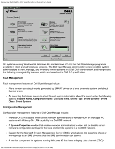
7 .Introduction: Dell OptiPl...Introduction: Dell OptiPlex GX1 Small-Form-Factor System User's Guidefile:///C|/infodev/2013/eDoc/OpGX1/UG/intro.htm [2/21/2013 11:47:09 AM]On systems running Windows 95, Windows 98, and Windows NT 4.0, the Dell OpenManage program isavailable in client and...
-
8 .Introduction: Dell OptiPl...Introduction: Dell OptiPlex GX1 Small-Form-Factor System User's Guidefile:///C|/infodev/2013/eDoc/OpGX1/UG/intro.htm [2/21/2013 11:47:09 AM]compliant video subsystem and monitor.Automated inventory control of one or more groups for the remote systems in a ...
-
9 .Introduction: Dell OptiPl...Introduction: Dell OptiPlex GX1 Small-Form-Factor System User's Guidefile:///C|/infodev/2013/eDoc/OpGX1/UG/intro.htm [2/21/2013 11:47:09 AM]Wakeup On LANThe Wakeup On LAN feature allows you to remotely turn on a Managed PC system that is in a sleep state.T...
-
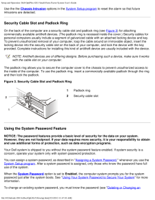
10 .Introduction: Dell OptiPl...Introduction: Dell OptiPlex GX1 Small-Form-Factor System User's Guidefile:///C|/infodev/2013/eDoc/OpGX1/UG/intro.htm [2/21/2013 11:47:09 AM]and then lock the padlock.On the back of the computer are a security cable slot and padlock ring (see Figure 3 in "...
-
11 .Introduction: Dell OptiPl...Introduction: Dell OptiPlex GX1 Small-Form-Factor System User's Guidefile:///C|/infodev/2013/eDoc/OpGX1/UG/intro.htm [2/21/2013 11:47:09 AM]manufacturers to reduce air pollution by promoting energy-efficient computer products. The EPA estimatesthat use of ...
-
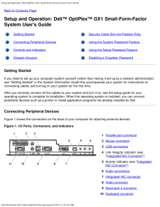
12 .Setup and Operation: Dell...Setup and Operation: Dell OptiPlex GX1 Small-Form-Factor System User's Guidefile:///C|/infodev/2013/eDoc/OpGX1/UG/setup.htm [2/21/2013 11:47:10 AM]Back to Contents PageSetup and Operation: DellTM OptiPlexTM GX1 Small-Form-FactorSystem User's GuideGetting S...
-
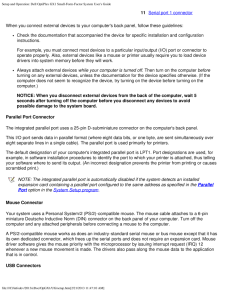
13 .Setup and Operation: Dell...Setup and Operation: Dell OptiPlex GX1 Small-Form-Factor System User's Guidefile:///C|/infodev/2013/eDoc/OpGX1/UG/setup.htm [2/21/2013 11:47:10 AM]11Serial port 1 connectorWhen you connect external devices to your computer's back panel, follow these guidel...
-
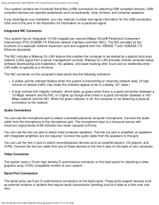
14 .Setup and Operation: Dell...Setup and Operation: Dell OptiPlex GX1 Small-Form-Factor System User's Guidefile:///C|/infodev/2013/eDoc/OpGX1/UG/setup.htm [2/21/2013 11:47:10 AM]Your system contains two Universal Serial Bus (USB) connectors for attaching USB-compliant devices. USB-compl...
-
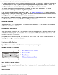
15 .Setup and Operation: Dell...Setup and Operation: Dell OptiPlex GX1 Small-Form-Factor System User's Guidefile:///C|/infodev/2013/eDoc/OpGX1/UG/setup.htm [2/21/2013 11:47:10 AM]The default designations for these integrated serial ports are COM1 for serial port 1 and COM2 for serial por...
-
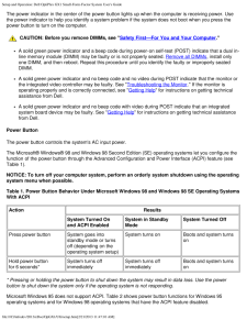
16 .Setup and Operation: Dell...Setup and Operation: Dell OptiPlex GX1 Small-Form-Factor System User's Guidefile:///C|/infodev/2013/eDoc/OpGX1/UG/setup.htm [2/21/2013 11:47:10 AM]The power indicator in the center of the power button lights up when the computer is receiving power. Usethe ...
-
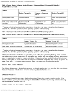
17 .Setup and Operation: Dell...Setup and Operation: Dell OptiPlex GX1 Small-Form-Factor System User's Guidefile:///C|/infodev/2013/eDoc/OpGX1/UG/setup.htm [2/21/2013 11:47:10 AM]Table 2. Power Button Behavior Under Microsoft Windows 95 and Windows 98 (With DellAutoShutdown Loaded)Action...
-
18 .Setup and Operation: Dell...Setup and Operation: Dell OptiPlex GX1 Small-Form-Factor System User's Guidefile:///C|/infodev/2013/eDoc/OpGX1/UG/setup.htm [2/21/2013 11:47:10 AM]Use the the Chassis Intrusion options in the System Setup program to reset the alarm so that futureintrusio...
-
19 .Setup and Operation: Dell...Setup and Operation: Dell OptiPlex GX1 Small-Form-Factor System User's Guidefile:///C|/infodev/2013/eDoc/OpGX1/UG/setup.htm [2/21/2013 11:47:10 AM]Existing System Password "). If you assign and later forget a system password, you must remove thecomputer co...
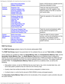
-
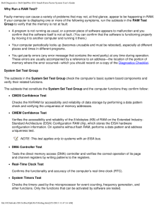
20 .Setup and Operation: Dell...Setup and Operation: Dell OptiPlex GX1 Small-Form-Factor System User's Guidefile:///C|/infodev/2013/eDoc/OpGX1/UG/setup.htm [2/21/2013 11:47:10 AM]5. To confirm your password, type it a second time and press
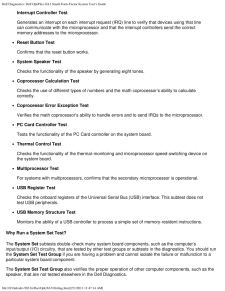
.The password setting changes to Enabled ... -
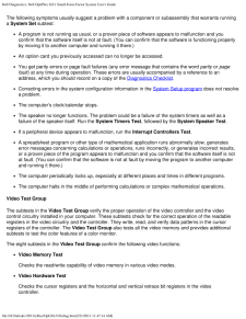
21 .Setup and Operation: Dell...Setup and Operation: Dell OptiPlex GX1 Small-Form-Factor System User's Guidefile:///C|/infodev/2013/eDoc/OpGX1/UG/setup.htm [2/21/2013 11:47:10 AM]To delete or change an existing system password, perform the following steps:1. Enter the System Setup progra...
-
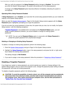
22 .Setup and Operation: Dell...Setup and Operation: Dell OptiPlex GX1 Small-Form-Factor System User's Guidefile:///C|/infodev/2013/eDoc/OpGX1/UG/setup.htm [2/21/2013 11:47:10 AM]Operating Your System With a Setup Password EnabledIf Setup Password is set to Enabled, you must enter the co...
-
23 .Setup and Operation: Dell...Setup and Operation: Dell OptiPlex GX1 Small-Form-Factor System User's Guidefile:///C|/infodev/2013/eDoc/OpGX1/UG/setup.htm [2/21/2013 11:47:10 AM]3. Replace the computer cover.4. Reconnect your computer and peripherals to an electrical outlet, and then tu...
-
24 .Using the System Setup Pr...Using the System Setup Program: Dell OptiPlex GX1 Small-Form-Factor System User's Guidefile:///C|/infodev/2013/eDoc/OpGX1/UG/sysetup.htm [2/21/2013 11:47:11 AM]Back to Contents PageUsing the System Setup Program: DellTM OptiPlexTM GX1 Small-Form-Factor Sys...
-
25 .Using the System Setup Pr...Using the System Setup Program: Dell OptiPlex GX1 Small-Form-Factor System User's Guidefile:///C|/infodev/2013/eDoc/OpGX1/UG/sysetup.htm [2/21/2013 11:47:11 AM]logo screen.If you wait too long and your operating system begins to load into memory, let the ...
-
26 .Using the System Setup Pr...Using the System Setup Program: Dell OptiPlex GX1 Small-Form-Factor System User's Guidefile:///C|/infodev/2013/eDoc/OpGX1/UG/sysetup.htm [2/21/2013 11:47:11 AM]Information on the two System Setup screens is organized in five boxed areas:Configuration optio...
-
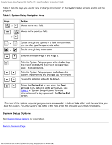
27 .Using the System Setup Pr...Using the System Setup Program: Dell OptiPlex GX1 Small-Form-Factor System User's Guidefile:///C|/infodev/2013/eDoc/OpGX1/UG/sysetup.htm [2/21/2013 11:47:11 AM]Table 1 lists the keys you use to view or change information on the System Setup screens and to ...
-
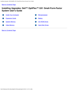
28 .Installing Upgrades: Dell...Installing Upgrades: Dell OptiPlex GX1 Small-Form-Factor System User's Guidefile:///C|/infodev/2013/eDoc/OpGX1/UG/install.htm [2/21/2013 11:47:12 AM]Back to Contents PageInstalling Upgrades: DellTM OptiPlexTM GX1 Small-Form-FactorSystem User's GuideInside ...
-
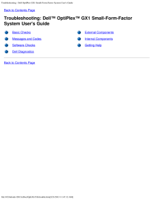
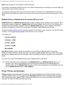
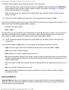
29 .Troubleshooting: Dell Op...Troubleshooting: Dell OptiPlex GX1 Small-Form-Factor System User's Guidefile:///C|/infodev/2013/eDoc/OpGX1/UG/trouble.htm [2/21/2013 11:47:12 AM]Back to Contents PageTroubleshooting: DellTM OptiPlexTM GX1 Small-Form-FactorSystem User's GuideBasic Checks E...
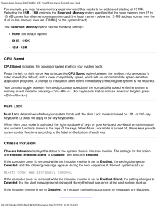
-
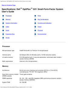
30 .Specifications: Dell Opti...Specifications: Dell OptiPlex GX1 Small-Form-Factor System User's Guidefile:///C|/infodev/2013/eDoc/OpGX1/UG/specs.htm [2/21/2013 11:47:12 AM]Back to Contents PageSpecifications: DellTM OptiPlexTM GX1 Small-Form-Factor SystemUser's GuideProcessor PortsMemo...
-
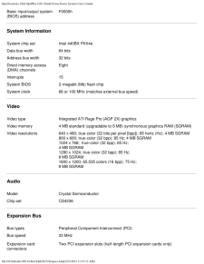
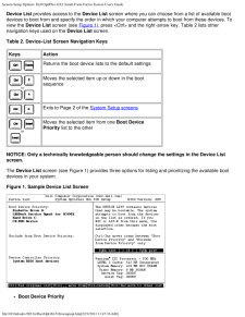
31 .Specifications: Dell Opti...Specifications: Dell OptiPlex GX1 Small-Form-Factor System User's Guidefile:///C|/infodev/2013/eDoc/OpGX1/UG/specs.htm [2/21/2013 11:47:12 AM]Basic input/output system(BIOS) addressF0000hSystem InformationSystem chip set Intel 440BX PIIX4eData bus width 64...
-
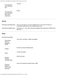
32 .Specifications: Dell Opti...Specifications: Dell OptiPlex GX1 Small-Form-Factor System User's Guidefile:///C|/infodev/2013/eDoc/OpGX1/UG/specs.htm [2/21/2013 11:47:12 AM]PCI expansion-card connectorsize120 pinsPCI expansion-card connectordata width(maximum)32 bitsDrivesExternally acc...
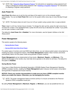
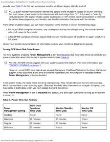
-
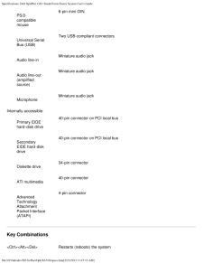
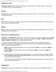
33 .Specifications: Dell Opti...Specifications: Dell OptiPlex GX1 Small-Form-Factor System User's Guidefile:///C|/infodev/2013/eDoc/OpGX1/UG/specs.htm [2/21/2013 11:47:12 AM]PS/2-compatiblemouse6-pin mini-DINUniversal SerialBus (USB)Two USB-compliant connectorsAudio line-inMiniature audi...
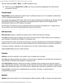
-
34 .Specifications: Dell Opti...Specifications: Dell OptiPlex GX1 Small-Form-Factor System User's Guidefile:///C|/infodev/2013/eDoc/OpGX1/UG/specs.htm [2/21/2013 11:47:12 AM]
<\> Toggles microprocessor speeds on 101-key keyboard (in MS-DOS(R) realmode only) <#> Toggle... -
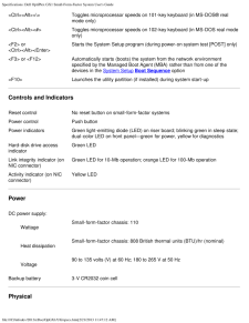
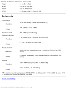
35 .Specifications: Dell Opti...Specifications: Dell OptiPlex GX1 Small-Form-Factor System User's Guidefile:///C|/infodev/2013/eDoc/OpGX1/UG/specs.htm [2/21/2013 11:47:12 AM]Height 9.1 cm (3.6 inches)Width 31.8 cm (12.5 inches)Depth 37.8 cm (14.9 inches)Weight 6.6 kilograms (kg) (14.5 po...
-
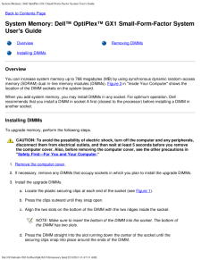
36 .System Memory: Dell OptiP...System Memory: Dell OptiPlex GX1 Small-Form-Factor System User's Guidefile:///C|/infodev/2013/eDoc/OpGX1/UG/memory.htm [2/21/2013 11:47:13 AM]Back to Contents PageSystem Memory: DellTM OptiPlexTM GX1 Small-Form-Factor SystemUser's GuideOverview Removing DI...
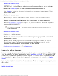
-
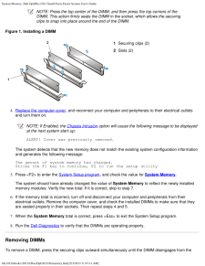
37 .System Memory: Dell OptiP...System Memory: Dell OptiPlex GX1 Small-Form-Factor System User's Guidefile:///C|/infodev/2013/eDoc/OpGX1/UG/memory.htm [2/21/2013 11:47:13 AM]NOTE: Press the top center of the DIMM, and then press the top corners of theDIMM. This action firmly seats the DI...
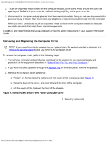
-
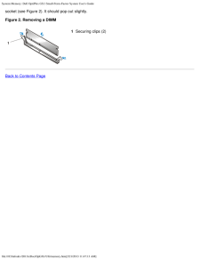
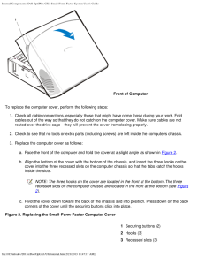
38 .System Memory: Dell OptiP...System Memory: Dell OptiPlex GX1 Small-Form-Factor System User's Guidefile:///C|/infodev/2013/eDoc/OpGX1/UG/memory.htm [2/21/2013 11:47:13 AM]socket (see Figure 2). It should pop out slightly.Figure 2. Removing a DIMM1Securing clips (2)Back to Contents Pag...
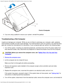
-
39 .Dell Diagnostics: Dell Op...Dell Diagnostics: Dell OptiPlex GX1 Small-Form-Factor System User's Guidefile:///C|/infodev/2013/eDoc/OpGX1/UG/diag.htm [2/21/2013 11:47:14 AM]Back to Contents PageDellTM Diagnostics: Dell OptiPlexTM GX1 Small-Form-Factor SystemUser's Guide Overview Confi...
-
40 .Dell Diagnostics: Dell Op...Dell Diagnostics: Dell OptiPlex GX1 Small-Form-Factor System User's Guidefile:///C|/infodev/2013/eDoc/OpGX1/UG/diag.htm [2/21/2013 11:47:14 AM]group Status messages that inform you whether test groups or subtests were completed successfullyError messages t...
-
41 .Dell Diagnostics: Dell Op...Dell Diagnostics: Dell OptiPlex GX1 Small-Form-Factor System User's Guidefile:///C|/infodev/2013/eDoc/OpGX1/UG/diag.htm [2/21/2013 11:47:14 AM]Starting the Dell DiagnosticsPerform the following steps to start the diagnostics:1. Turn on the system.2. Enter ...
-
42 .Dell Diagnostics: Dell Op...Dell Diagnostics: Dell OptiPlex GX1 Small-Form-Factor System User's Guidefile:///C|/infodev/2013/eDoc/OpGX1/UG/diag.htm [2/21/2013 11:47:14 AM]How to Use the Dell DiagnosticsWhen you select Run Specific Tests from the Diagnostics Menu , the main screen of...
-
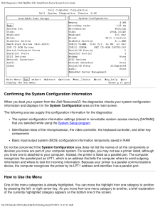
43 .Dell Diagnostics: Dell Op...Dell Diagnostics: Dell OptiPlex GX1 Small-Form-Factor System User's Guidefile:///C|/infodev/2013/eDoc/OpGX1/UG/diag.htm [2/21/2013 11:47:14 AM]Confirming the System Configuration InformationWhen you boot your system from the Dell ResourceCD , the diagnosti...
-
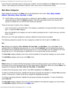
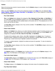
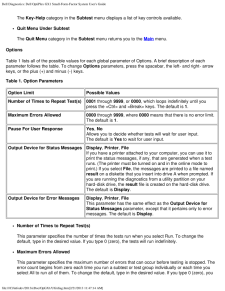
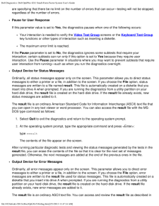
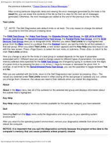
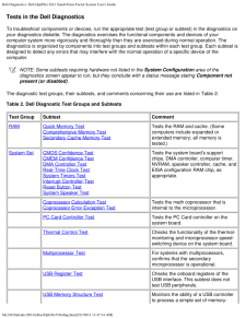
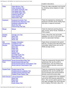
44 .Dell Diagnostics: Dell Op...Dell Diagnostics: Dell OptiPlex GX1 Small-Form-Factor System User's Guidefile:///C|/infodev/2013/eDoc/OpGX1/UG/diag.htm [2/21/2013 11:47:14 AM]If you want more information about a test group or subtest, move the highlight to the About option and press45 .Dell Diagnostics: Dell Op...Dell Diagnostics: Dell OptiPlex GX1 Small-Form-Factor System User's Guidefile:///C|/infodev/2013/eDoc/OpGX1/UG/diag.htm [2/21/2013 11:47:14 AM]SubtestMost of the test groups consist of several subtests. Use the Subtest category to select individual subtes...46 .Dell Diagnostics: Dell Op...Dell Diagnostics: Dell OptiPlex GX1 Small-Form-Factor System User's Guidefile:///C|/infodev/2013/eDoc/OpGX1/UG/diag.htm [2/21/2013 11:47:14 AM]The Key-Help category in the Subtest menu displays a list of key controls available. Quit Menu Under SubtestThe Q...47 .Dell Diagnostics: Dell Op...Dell Diagnostics: Dell OptiPlex GX1 Small-Form-Factor System User's Guidefile:///C|/infodev/2013/eDoc/OpGX1/UG/diag.htm [2/21/2013 11:47:14 AM]are specifying that there be no limit on the number of errors that can occur-testing will not be stopped,regardle...48 .Dell Diagnostics: Dell Op...Dell Diagnostics: Dell OptiPlex GX1 Small-Form-Factor System User's Guidefile:///C|/infodev/2013/eDoc/OpGX1/UG/diag.htm [2/21/2013 11:47:14 AM]the previous subsection, " Output Device for Status Messages ."After running particular diagnostic tests and view...49 .Dell Diagnostics: Dell Op...Dell Diagnostics: Dell OptiPlex GX1 Small-Form-Factor System User's Guidefile:///C|/infodev/2013/eDoc/OpGX1/UG/diag.htm [2/21/2013 11:47:14 AM]Tests in the Dell DiagnosticsTo troubleshoot components or devices, run the appropriate test (test group or subte...50 .Dell Diagnostics: Dell Op...Dell Diagnostics: Dell OptiPlex GX1 Small-Form-Factor System User's Guidefile:///C|/infodev/2013/eDoc/OpGX1/UG/diag.htm [2/21/2013 11:47:14 AM]resident instructions.Video Video Memory TestVideo Hardware TestText Mode Character TestText Mode Color TestText ...51 .Dell Diagnostics: Dell Op...Dell Diagnostics: Dell OptiPlex GX1 Small-Form-Factor System User's Guidefile:///C|/infodev/2013/eDoc/OpGX1/UG/diag.htm [2/21/2013 11:47:14 AM]Eject Removable MediaDisplay Informationtypes of SCSI devices installed and theresources allocated to them.Networ...52 .Dell Diagnostics: Dell Op...Dell Diagnostics: Dell OptiPlex GX1 Small-Form-Factor System User's Guidefile:///C|/infodev/2013/eDoc/OpGX1/UG/diag.htm [2/21/2013 11:47:14 AM]Why Run a RAM Test?Faulty memory can cause a variety of problems that may not, at first glance, appear to be happ...53 .Dell Diagnostics: Dell Op...Dell Diagnostics: Dell OptiPlex GX1 Small-Form-Factor System User's Guidefile:///C|/infodev/2013/eDoc/OpGX1/UG/diag.htm [2/21/2013 11:47:14 AM]Interrupt Controller TestGenerates an interrupt on each interrupt request (IRQ) line to verify that devices using...54 .Dell Diagnostics: Dell Op...Dell Diagnostics: Dell OptiPlex GX1 Small-Form-Factor System User's Guidefile:///C|/infodev/2013/eDoc/OpGX1/UG/diag.htm [2/21/2013 11:47:14 AM]The following symptoms usually suggest a problem with a component or subassembly that warrants runninga System Se...55 .Dell Diagnostics: Dell Op...Dell Diagnostics: Dell OptiPlex GX1 Small-Form-Factor System User's Guidefile:///C|/infodev/2013/eDoc/OpGX1/UG/diag.htm [2/21/2013 11:47:14 AM]Text Mode Character TestChecks the video subsystem's ability to present data in text modes.Text Mode Color TestCh...56 .Dell Diagnostics: Dell Op...Dell Diagnostics: Dell OptiPlex GX1 Small-Form-Factor System User's Guidefile:///C|/infodev/2013/eDoc/OpGX1/UG/diag.htm [2/21/2013 11:47:14 AM]Mode Pages Test, and Graphics Mode Test.Keyboard Test GroupThe subtests in the Keyboard Test Group verify the cor...57 .Dell Diagnostics: Dell Op...Dell Diagnostics: Dell OptiPlex GX1 Small-Form-Factor System User's Guidefile:///C|/infodev/2013/eDoc/OpGX1/UG/diag.htm [2/21/2013 11:47:14 AM]Mouse TestThe Mouse Test checks the functionality of the mouse controller (which coordinates cursor movement on t...58 .Dell Diagnostics: Dell Op...Dell Diagnostics: Dell OptiPlex GX1 Small-Form-Factor System User's Guidefile:///C|/infodev/2013/eDoc/OpGX1/UG/diag.htm [2/21/2013 11:47:14 AM]diskette can be written to correctlyWhy Run a Diskette Drives Test?Very often, a diskette drive problem may first...59 .Dell Diagnostics: Dell Op...Dell Diagnostics: Dell OptiPlex GX1 Small-Form-Factor System User's Guidefile:///C|/infodev/2013/eDoc/OpGX1/UG/diag.htm [2/21/2013 11:47:14 AM]Similar to the Read Test, but no data is transferred from the drive to the system.Write TestPositions the read/wr...60 .Dell Diagnostics: Dell Op...Dell Diagnostics: Dell OptiPlex GX1 Small-Form-Factor System User's Guidefile:///C|/infodev/2013/eDoc/OpGX1/UG/diag.htm [2/21/2013 11:47:14 AM]such as a printer and a mouse, that are connected to the computer through a serial or infrared port. Thesubtests ...61 .Dell Diagnostics: Dell Op...Dell Diagnostics: Dell OptiPlex GX1 Small-Form-Factor System User's Guidefile:///C|/infodev/2013/eDoc/OpGX1/UG/diag.htm [2/21/2013 11:47:14 AM]If a peripheral works intermittently or produces intermittent errors, the port may be faulty.If the computer disp...62 .Dell Diagnostics: Dell Op...Dell Diagnostics: Dell OptiPlex GX1 Small-Form-Factor System User's Guidefile:///C|/infodev/2013/eDoc/OpGX1/UG/diag.htm [2/21/2013 11:47:14 AM]Another possible cause for errors is the external device. Use the documentation that came with theperipheral to t...63 .Dell Diagnostics: Dell Op...Dell Diagnostics: Dell OptiPlex GX1 Small-Form-Factor System User's Guidefile:///C|/infodev/2013/eDoc/OpGX1/UG/diag.htm [2/21/2013 11:47:14 AM]Causes the CD-ROM drive to begin playing the first audio track on an audio CD. To determinewhether the test passe...64 .Dell Diagnostics: Dell Op...Dell Diagnostics: Dell OptiPlex GX1 Small-Form-Factor System User's Guidefile:///C|/infodev/2013/eDoc/OpGX1/UG/diag.htm [2/21/2013 11:47:14 AM]Places the controller into its various internal loopback modes and tests its ability to transmit andreceive data....65 .Dell Diagnostics: Dell Op...Dell Diagnostics: Dell OptiPlex GX1 Small-Form-Factor System User's Guidefile:///C|/infodev/2013/eDoc/OpGX1/UG/diag.htm [2/21/2013 11:47:14 AM]NOTE: The following subtests are only applicable for systems with built-in speakers.The eleven subtests in the Au...66 .Dell Diagnostics: Dell Op...Dell Diagnostics: Dell OptiPlex GX1 Small-Form-Factor System User's Guidefile:///C|/infodev/2013/eDoc/OpGX1/UG/diag.htm [2/21/2013 11:47:14 AM]If you do not hear sounds from your built-in speakers when you expect to, it is possible that your operatingsyste...67 .Dell Diagnostics: Dell Op...Dell Diagnostics: Dell OptiPlex GX1 Small-Form-Factor System User's Guidefile:///C|/infodev/2013/eDoc/OpGX1/UG/diag.htm [2/21/2013 11:47:14 AM]Error MessagesWhen you run a test group or subtest in the Dell Diagnostics, error messages may result. These part...68 .System Setup Options: Del...System Setup Options: Dell OptiPlex GX1 Small-Form-Factor System User's Guidefile:///C|/infodev/2013/eDoc/OpGX1/UG/setupopt.htm [2/21/2013 11:47:16 AM]Back to Contents PageSystem Setup Options: DellTM OptiPlexTM GX1 Small-Form-FactorSystem User's GuideTime...69 .System Setup Options: Del...System Setup Options: Dell OptiPlex GX1 Small-Form-Factor System User's Guidefile:///C|/infodev/2013/eDoc/OpGX1/UG/setupopt.htm [2/21/2013 11:47:16 AM]Date resets the date on the computer's internal calendar.Your system automatically displays the day of th...70 .System Setup Options: Del...System Setup Options: Dell OptiPlex GX1 Small-Form-Factor System User's Guidefile:///C|/infodev/2013/eDoc/OpGX1/UG/setupopt.htm [2/21/2013 11:47:16 AM]The System Setup program reports hard-disk drives in one of two ways:Newer hard-disk drives and all hard-...71 .System Setup Options: Del...System Setup Options: Dell OptiPlex GX1 Small-Form-Factor System User's Guidefile:///C|/infodev/2013/eDoc/OpGX1/UG/setupopt.htm [2/21/2013 11:47:16 AM]For example, you may have a memory expansion card that needs to be addressed starting at 15 MB.Selecting ...72 .System Setup Options: Del...System Setup Options: Dell OptiPlex GX1 Small-Form-Factor System User's Guidefile:///C|/infodev/2013/eDoc/OpGX1/UG/setupopt.htm [2/21/2013 11:47:16 AM]To reset the Detected setting, enter the System Setup program during the system's power-on self-test(POS...73 .System Setup Options: Del...System Setup Options: Dell OptiPlex GX1 Small-Form-Factor System User's Guidefile:///C|/infodev/2013/eDoc/OpGX1/UG/setupopt.htm [2/21/2013 11:47:16 AM]Disabled by JumperNOTE: See " Using the System Password Feature " for instructions on assigning a system ...74 .System Setup Options: Del...System Setup Options: Dell OptiPlex GX1 Small-Form-Factor System User's Guidefile:///C|/infodev/2013/eDoc/OpGX1/UG/setupopt.htm [2/21/2013 11:47:16 AM]Device List provides access to the Device List screen where you can choose from a list of available boot...75 .System Setup Options: Del...System Setup Options: Dell OptiPlex GX1 Small-Form-Factor System User's Guidefile:///C|/infodev/2013/eDoc/OpGX1/UG/setupopt.htm [2/21/2013 11:47:16 AM]The Boot Device Priority option lists all bootable devices (hard-disk drives, CD-ROM drives,and so on) th...76 .System Setup Options: Del...System Setup Options: Dell OptiPlex GX1 Small-Form-Factor System User's Guidefile:///C|/infodev/2013/eDoc/OpGX1/UG/setupopt.htm [2/21/2013 11:47:16 AM]NOTE: See " Using the Setup Password Feature " for instructions on assigning a setup password andusing or...77 .System Setup Options: Del...System Setup Options: Dell OptiPlex GX1 Small-Form-Factor System User's Guidefile:///C|/infodev/2013/eDoc/OpGX1/UG/setupopt.htm [2/21/2013 11:47:16 AM]periods (see Table 3) for the two successive monitor shutdown stages, standby and off.NOTE: Each monitor...78 .System Setup Options: Del...System Setup Options: Dell OptiPlex GX1 Small-Form-Factor System User's Guidefile:///C|/infodev/2013/eDoc/OpGX1/UG/setupopt.htm [2/21/2013 11:47:16 AM]Wakeup On LANWakeup On LAN determines whether the Wakeup On LAN feature is set to On or Off. You must re...79 .System Setup Options: Del...System Setup Options: Dell OptiPlex GX1 Small-Form-Factor System User's Guidefile:///C|/infodev/2013/eDoc/OpGX1/UG/setupopt.htm [2/21/2013 11:47:16 AM]alternate addresses 278h or 3BCh, or to Off to disable the port.NOTE: Do not set Parallel Port to 278h i...80 .System Setup Options: Del...System Setup Options: Dell OptiPlex GX1 Small-Form-Factor System User's Guidefile:///C|/infodev/2013/eDoc/OpGX1/UG/setupopt.htm [2/21/2013 11:47:16 AM]effect immediately (rebooting the system is not required).System Data OptionsThe following options, which...81 .System Setup Options: Del...System Setup Options: Dell OptiPlex GX1 Small-Form-Factor System User's Guidefile:///C|/infodev/2013/eDoc/OpGX1/UG/setupopt.htm [2/21/2013 11:47:16 AM]changing a jumper setting, anyone can access the data stored on your hard-disk drive.Before you can assig...82 .System Setup Options: Del...System Setup Options: Dell OptiPlex GX1 Small-Form-Factor System User's Guidefile:///C|/infodev/2013/eDoc/OpGX1/UG/setupopt.htm [2/21/2013 11:47:16 AM]system off and then on again.Using Your System Password to Secure Your SystemWhenever you turn on your sy...83 .System Setup Options: Del...System Setup Options: Dell OptiPlex GX1 Small-Form-Factor System User's Guidefile:///C|/infodev/2013/eDoc/OpGX1/UG/setupopt.htm [2/21/2013 11:47:16 AM]set to Unlocked.Press the
key combination to move to Page 2 of the System Setup screens.2. Rebo...
84 .System Setup Options: Del...System Setup Options: Dell OptiPlex GX1 Small-Form-Factor System User's Guidefile:///C|/infodev/2013/eDoc/OpGX1/UG/setupopt.htm [2/21/2013 11:47:16 AM]After you verify the password, the Setup Password setting changes to Enabled . The next timeyou enter th...85 .System Setup Options: Del...System Setup Options: Dell OptiPlex GX1 Small-Form-Factor System User's Guidefile:///C|/infodev/2013/eDoc/OpGX1/UG/setupopt.htm [2/21/2013 11:47:16 AM]1. Remove the computer cover . NOTICE: Verify that the AC power cable is removed before changing any ju...86 .Internal Components: Dell...Internal Components: Dell OptiPlex GX1 Small-Form-Factor System User's Guidefile:///C|/infodev/2013/eDoc/OpGX1/UG/internal.htm [2/21/2013 11:47:17 AM]Back to Contents PageInternal Components: DellTM OptiPlexTM GX1 Small-Form-FactorSystem User's GuideOvervi...87 .Internal Components: Dell...Internal Components: Dell OptiPlex GX1 Small-Form-Factor System User's Guidefile:///C|/infodev/2013/eDoc/OpGX1/UG/internal.htm [2/21/2013 11:47:17 AM]2. Touch an unpainted metal surface on the computer chassis, such as the metal around the card-slotopening...88 .Internal Components: Dell...Internal Components: Dell OptiPlex GX1 Small-Form-Factor System User's Guidefile:///C|/infodev/2013/eDoc/OpGX1/UG/internal.htm [2/21/2013 11:47:17 AM]Front of ComputerTo replace the computer cover, perform the following steps:1. Check all cable connections...89 .Internal Components: Dell...Internal Components: Dell OptiPlex GX1 Small-Form-Factor System User's Guidefile:///C|/infodev/2013/eDoc/OpGX1/UG/internal.htm [2/21/2013 11:47:17 AM]Front of Computer4. If you are using a padlock to secure your system, reinstall the padlock.Troubleshootin...90 .Internal Components: Dell...Internal Components: Dell OptiPlex GX1 Small-Form-Factor System User's Guidefile:///C|/infodev/2013/eDoc/OpGX1/UG/internal.htm [2/21/2013 11:47:17 AM]expansion cards you removed in step 4. 7. Replace the computer cover, and reconnect the system to an elect...91 .Internal Components: Dell...Internal Components: Dell OptiPlex GX1 Small-Form-Factor System User's Guidefile:///C|/infodev/2013/eDoc/OpGX1/UG/internal.htm [2/21/2013 11:47:17 AM]If an error message indicates a problem with the battery or if the System Setup program loses the systemc...92 .Internal Components: Dell...Internal Components: Dell OptiPlex GX1 Small-Form-Factor System User's Guidefile:///C|/infodev/2013/eDoc/OpGX1/UG/internal.htm [2/21/2013 11:47:17 AM]If the tests complete successfully, proceed to step 8. If any of the tests fail, see " Getting Help " fori...93 .Internal Components: Dell...Internal Components: Dell OptiPlex GX1 Small-Form-Factor System User's Guidefile:///C|/infodev/2013/eDoc/OpGX1/UG/internal.htm [2/21/2013 11:47:17 AM]monitor, the monitor interface cable, or the integrated video subsystem.Before attempting to troubleshoot ...94 .Internal Components: Dell...Internal Components: Dell OptiPlex GX1 Small-Form-Factor System User's Guidefile:///C|/infodev/2013/eDoc/OpGX1/UG/internal.htm [2/21/2013 11:47:17 AM]1. Enter the System Setup program , and verify that the problem drive is configured correctly. Make anynec...95 .External Components: Dell...External Components: Dell GX1 Small-Form-Factor System User's Guidefile:///C|/infodev/2013/eDoc/OpGX1/UG/external.htm [2/21/2013 11:47:18 AM]Back to Contents PageExternal Components: DellTM OptiPlexTM GX1 Small-Form-FactorSystem User's GuideOverview Troubl...96 .External Components: Dell...External Components: Dell GX1 Small-Form-Factor System User's Guidefile:///C|/infodev/2013/eDoc/OpGX1/UG/external.htm [2/21/2013 11:47:18 AM]If the tests complete successfully, the original monitor was faulty. If the tests still fail, the videocontroller o...97 .External Components: Dell...External Components: Dell GX1 Small-Form-Factor System User's Guidefile:///C|/infodev/2013/eDoc/OpGX1/UG/external.htm [2/21/2013 11:47:18 AM]procedures in "Troubleshooting Expansion Cards " to verify that the card is configured and installed correctly.If a...98 .External Components: Dell...External Components: Dell GX1 Small-Form-Factor System User's Guidefile:///C|/infodev/2013/eDoc/OpGX1/UG/external.htm [2/21/2013 11:47:18 AM]working cable, and turn on the parallel printer and computer.If the problem is resolved, the original printer cable...99 .Getting Help: Dell OptiPl...Getting Help: Dell OptiPlex GX1 Small-Form-Factor System User's Guidefile:///C|/infodev/2013/eDoc/OpGX1/UG/getting.htm [2/21/2013 11:47:19 AM]Back to Contents PageGetting Help: DellTM OptiPlexTM GX1 Small-Form-Factor SystemUser's GuideHelp Overview Contact...100 .Inside Your Computer: Del...Inside Your Computer: Dell OptiPlex GX1 Small-Form-Factor System User's Guidefile:///C|/infodev/2013/eDoc/OpGX1/UG/inside.htm [2/21/2013 11:47:19 AM]Back to Contents PageInside Your Computer: DellTM OptiPlexTM GX1 Small-Form-FactorSystem User's GuideOvervi...
